Debugging your kit in case you have problems
We will try to collect all we learn from helping out people that made soldering or other mistakes. The electronics of the PiDP-1 are surprisingly simple, so 99% of the time, if you give us the exact symptoms of what is not working, we know the cause. But first, have a look yourself.
If you can't fix your problem from the information on this page:
- Software install or soldering problems: (oscar@ceds.dev). Jose and Oscar both use this email address for the fastest reponse :-) We're pretty good at remote diagnosis, if you allow some time debugging with us, we'll get your machine going for sure.
- Spare parts: contact Jose (j.leon@ceds.dev). Operated on a trust basis: if you feel it's our fault (missing parts? That Never Happens™) the parts are free. Otherwise, we ask you for shipping and the cost of the parts.
New: also check the PiDP Tester page for the tester tool included in all kits after April 2026.
A single LED does not light up
99% of the time: you forgot to solder one of its pins, or the solder connections looks fine, but just reflow the solder.1% of the time: the LED is bad (never happened yet on 50 PiDP-1s, but you never know). Replace with one of the spares from the kit. Mind polarity. I think, if you put one LED in the wrong way (polarity), you get other recognisable symptoms too, but for sure that LED won't work. TBI.
A row of LEDs does not light up
30% of the time: reflow the pins of the 18-pin IC. It provides power to 8 different rows of 18 switches each.58% of the time: check the GPIO connector's soldering, actually just reflow all its pins.
~1% of the time: it sounds odd. Clean the GPIO solder pins with alcohol. Vodka is fine too. We've had two dozen cases with other PiDPs where excess solder flux made a weak short, but enough to cause problems.
0.001% of the time: the LED is bad (never happened yet on 50 PiDP-1s, but you never know. It never happened for a decade, then we had a few cases in the same batch of kits). Replace with one of the spares from the kit. Mind polarity.
I think, if you put one LED in the wrong way (polarity), you get other recognisable symptoms too, but for sure that LED won't work. TBI.
A column of LEDs does not light up
(i.e., across multiple rows, LED number 6 or whatever does not work)60% of the time: check the 18 resistors near the GPIO. One is not or badly soldered. Reflow.
10% of the time: check the soldering on the 18-pin chip. One of its pins might need reflowing. Also: reinsert the chip, maybe a pin did not connect into the chip socket.
20% of the time: check the GPIO pins for the columns (see schematic further down). There's one GPIO pin driving every column.
0.001% of the time: the LED is bad (never happened yet on 50 PiDP-1s, but you never know. It never happened for a decade, then we had a few cases in the same batch of kits). Replace with one of the spares from the kit. Mind polarity.
I think, if you put one LED in the wrong way (polarity), you get other recognisable symptoms too, but for sure that LED won't work. TBI.

A single switch does not give a signal in the test program
You know about the DEP switch, right? It toggles up, not down... :-)95% of the time: if one switch does not work, first reflow its solder pins. Also reflow the solder points of the diode above/below/next to it.
5% of the time: If that does not work, maybe the switch died?
99% of deaths are due to overheating during soldering. But bad switches are also known to exist.
You can test the switch with a multimeter: there should not be a connection between middle and upper pin if the switch is up, there should be ~0 ohms if the switch is down.
--> if this is not the case: replace switch with a spare from the kit.
You can also test another way: short the upper and middle pins with a bit of wire (or the clipped-off lead from one of the parts you soldered on).
-->Does that give the switch signal in the test program? If yes, then you have a bad switch. Replace with one of the spares in the kit.
It is never necessary to desolder a switch because you think it might be bad. First test (multimeter) if it makes contact between the middle and the top or bottom pin (depending in switch position), and test (short out the middle pin and the upper or lower pin) if that creates the switch signal. If you see the short between pins creates a signal and the switch itself does not, conclude the switch is bad!
A row of switches does not respond
did you put in all the 5 resistors around the chips? Reflow their solder.A column of switches does not respond
20% of the time: check the column GPIO pins (see schematic further down). There's one GPIO pin driving every column of switches.Nothing works. And that's in the test program.
But the Pi did boot up, right, you can use its GUI etc? --> no booting up? Is the SD card inserted, fully seated, properly initialised? --> does the Pi boot up when pulled out of the PiDP-1, but not when it is in? --> this is interesting, go to Special Case #1.Did you put in the ICs?
Did you put them in the right chip socket? The 74hc238 and 74hc138 have the same pin count, and are easily swapped. U1 is the 238, it sits in the middle of the 3 ICs
Did you put them in the wrong way round? Note their notch. It needs to point to the edge of the board.
Dead chips basically do not happen ever. Discount that possibility until the bitter end of your debugging.
The test program needs the simulator to be fully stopped, including the panel driver. Do pdpcontrol stop a couple of times, then run the test program again. Superstition :-)
Are you using an ancient version of the Pi OS? Before mid-2024, the OS drove the GPIO in another way...
switches work, LEDs don't
Check the above section on the ICs.did you put in the diode close to the the 18-pin IC? Reflow its solder pins. Check its polarity (stripe matches footprint)?
LEDs work, switches don't
Check the above section on the ICs. Did you swap the 74hc138 and 238 around?did you put in the 5 resistors around the chips? Reflow their solder.
test program works, simulator does not
You have a software setup problem, or maybe do not fully understand the PDP-1 simulator? At any rate, if the test program works, the hardware is good. 100% sure.Odd behaviour of the 8 control switches
You can be pretty sure that this is due to not connecting the rainbow wires/ribbon cable between the two PCBs correctly!Special Case #1: Pi only boots up when NOT inserted in the PiDP-1 board
This is bad. Power down, maybe something on the PiDP-1 board is unhealthy for the Pi.Contact us!
Use Kicad to explore the PCB interactively
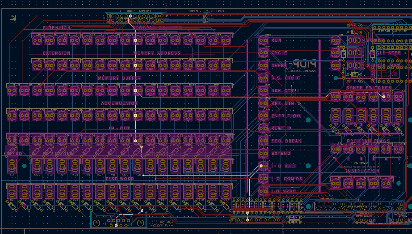
Essentially, the whole PCB consists of these row and column traces. Highlighting the row or column trace on the LED/switch that is not working will make it easy to see where you have to test for continuity. Test from solder pin to solder pin, as the highlighted trace in Kicad shows you.
Download PiDP-1 project files for Kicad
Download the board layout in SVG format
Download the schematics in SVG format
Understanding the theory of operation of the PiDP-1 circuit, to get clues on where the problem may lie, may be helpful. So the 18 'column' lines come straight out from GPIO pins, protected by a resistor. The 'row' lines are generated from 4 GPIO pins, that form an address. That address, through the 3 ICs on the PiDP-1, triggers one of the row lines to become active. This little animation explains the multiplexing that occurs constantly, so the human eye sees all LEDs being lit up. In reality, each row of LEDs is only lit up a fraction of each second:
When nothing helps: try with another Pi
We have seen a few Pi's (out of thousands) where the GPIO was damaged. But the Pi still happily works, the GPIO pins are just not doing as they're told.So it does make sense to try with another Pi. Even an old one, just to see if your problems go away.
Test program output explained
(WORK IN PROGRESS - see the test program's help text for now)Test program: 1 2 3 4 1 is the extend/extension/address switches, top row 1: leftmost digit is 2 for power sw 2 is the test word, bottom row 3: leftmost digits are is the sense sw, 176000 if 6 set 3: leftmost digit 2 = singinst, 4=singstep joystick left 010 000 right 004 000 ftr 002 000 thr fire 001 000 hyper 014 000 left 000 400 right 000 200 thr 000100 fire 00 00 40 hyper 00 0 600 000000 000001 000000 000000 sw meest rechts onderin Joy1 01 004 002 001 014 Joy 2000+400 200 100 040 600 st 001 stop 2 cont 1 ex 4 dep UP 2 readin 1 reader 4 tape 1
- If you hit the end of the page. I am sorry! Contact us for help, we'll get your board going:
- Software install or soldering problems: Ivan (i.poveda@ceds.dev) is the first responder, Oscar (oscar@ceds.dev) helps as well. Email both of us for the fastest response :-) We're pretty good at remote diagnosis, if you allow some time debugging with us, we'll get your machine going for sure.
- Spare parts: contact Jose (j.leon@ceds.dev). Operated on a trust basis: if you feel it's our fault (missing parts? That Never Happens™) the parts are free. Otherwise, we ask you for shipping and the cost of the parts.