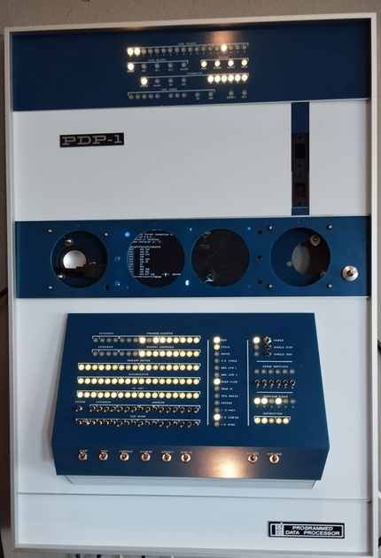
Follow-up: Building Instructions for the PiDP-1 Rack
Building the Rack part of the PiDP-1 should take about 2 hours extra.
Tools required: Soldering iron, side cutter, Phillips screwdriver.
We're building the rack parts from top to bottom in these instructions:
- the I/O Panel
- the Paper Tape Panel
- the Lawrence Livermore Speaker Panel
And the bottom panel below that is just a blank panel, although it will be adorned by a DEC badge and optionally, a Pi 5 power button if you want.
The panels add features to the PiDP-1, but are not required. Feel free to just put the cover panels in the rack and use your PiDP-1 already, if you don't have time to construct everything right now.
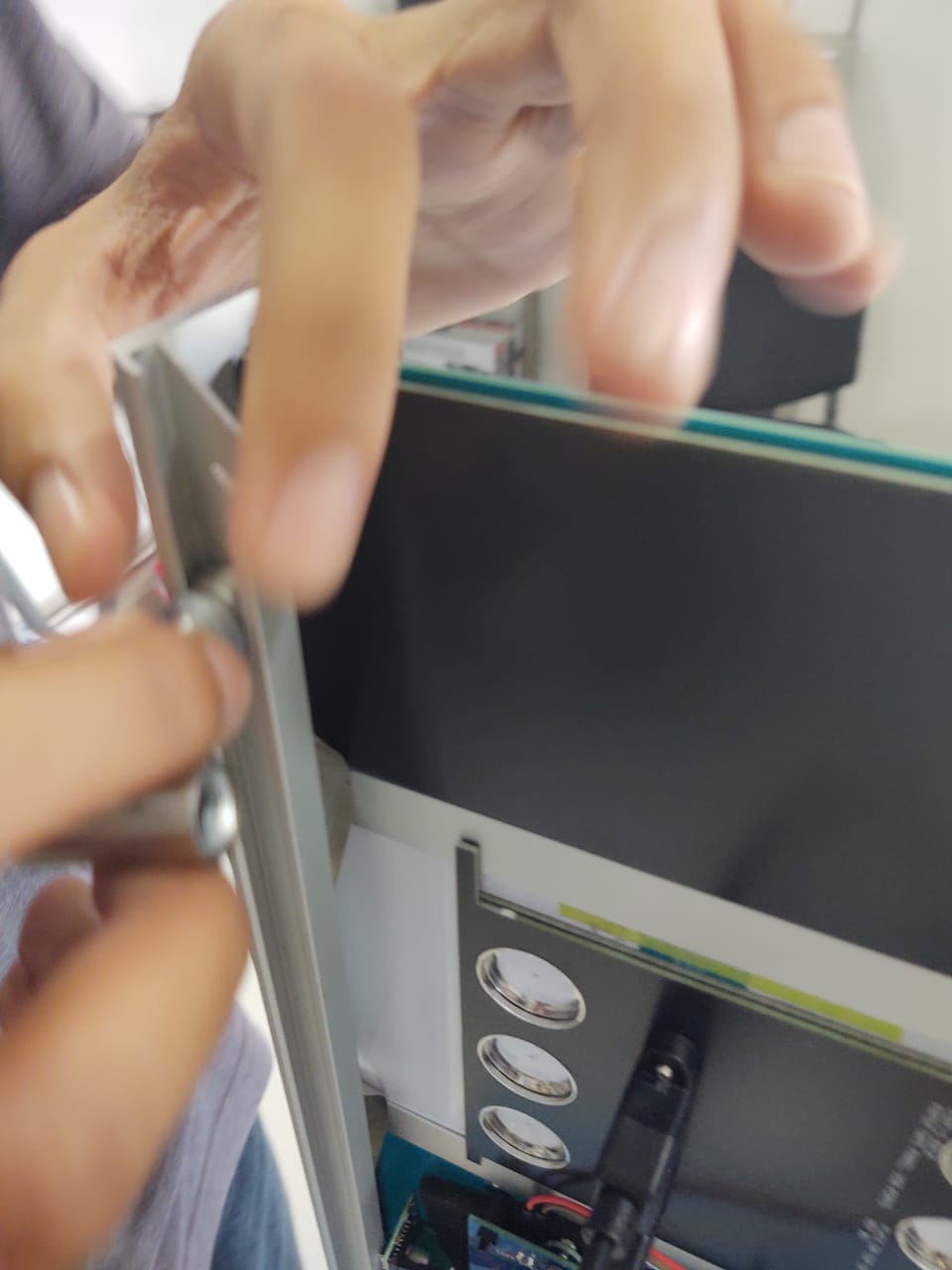
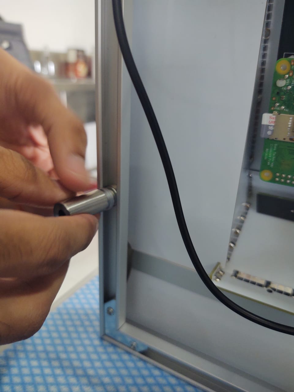
 temporary low-quality prototype photo...
Rack version: build the I/O Panel
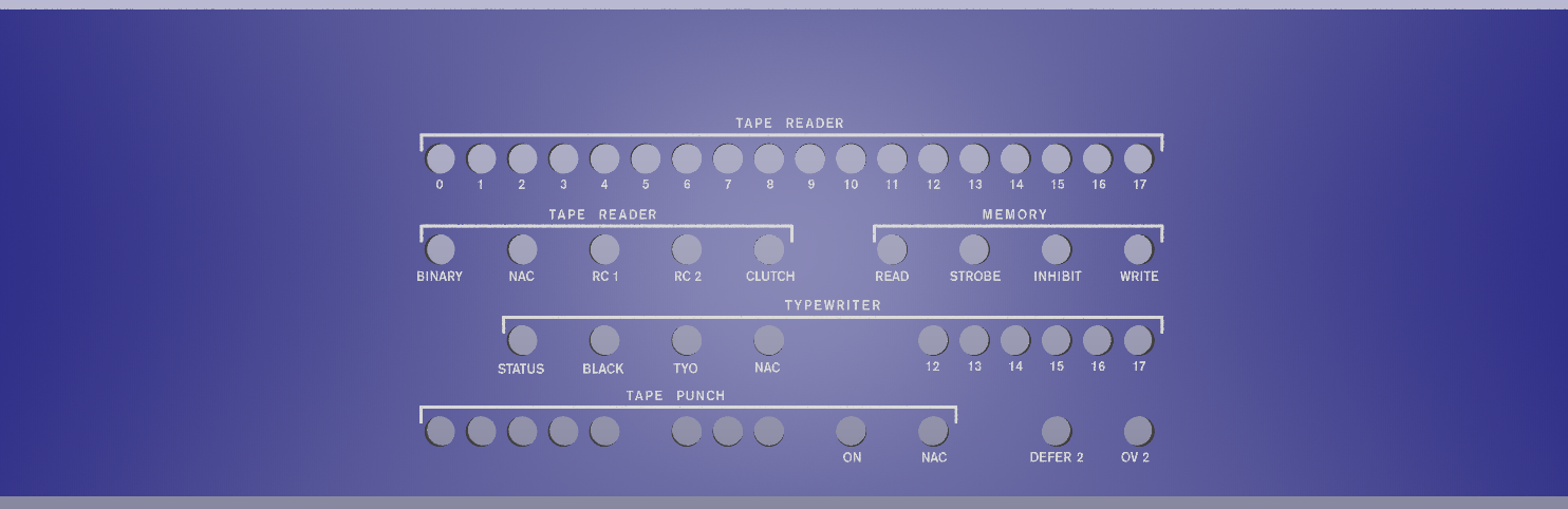
I/O Panel: Overview
Solder up the I/O Panel PCB
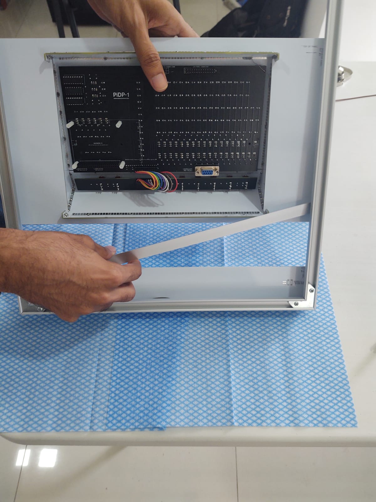
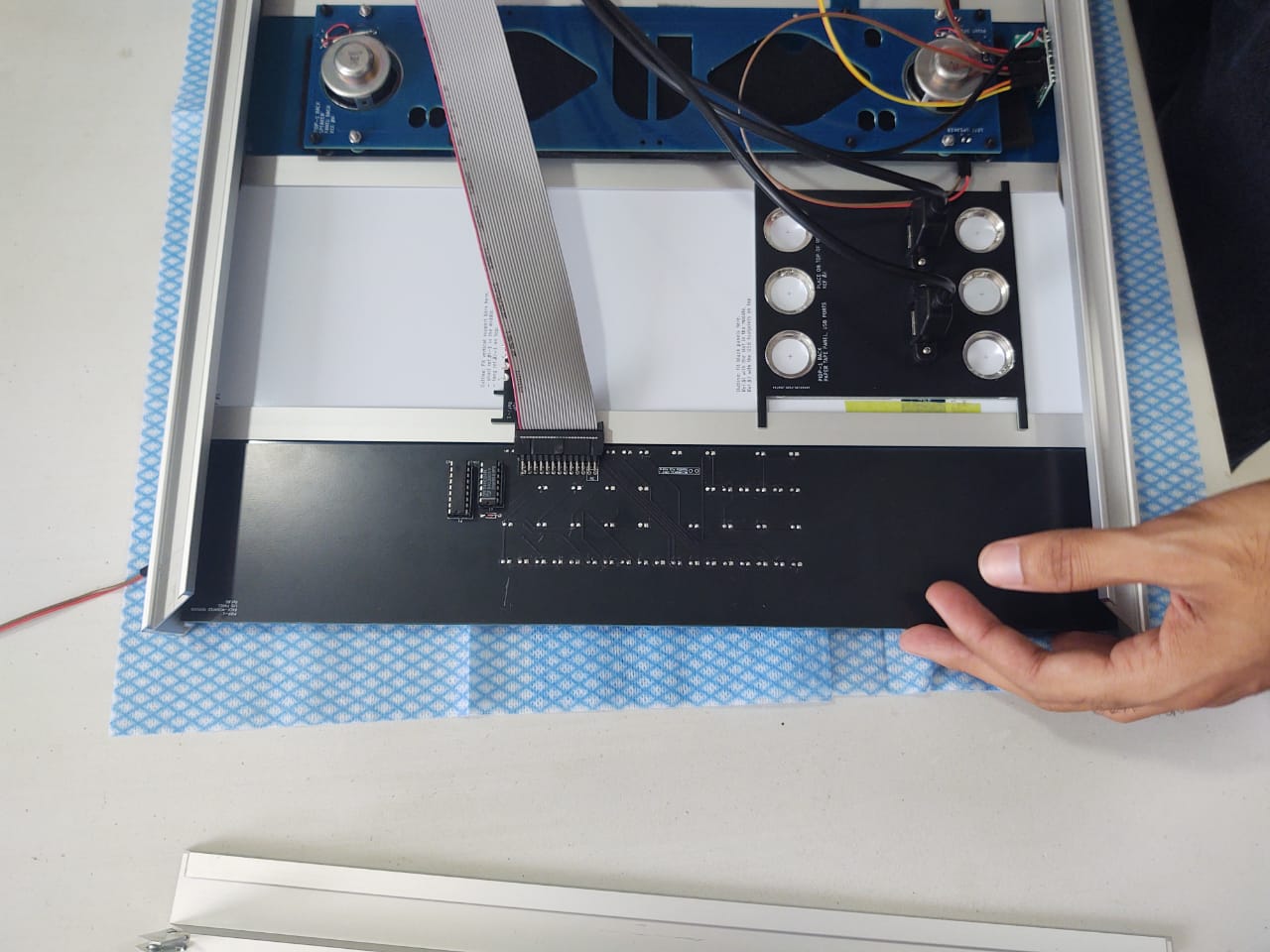
The IO panel consists of two parts - a cover panel (Ref.#F) and a circuit board (Ref.#Q). The circuit board is connected with a ribbon cable to the connector at the top of the PiDP-1 PCB. Please make sure you do not plug the ribbon cable in twisted: the red stripe of the connector cable should be on the same side on either end.
Soldering:
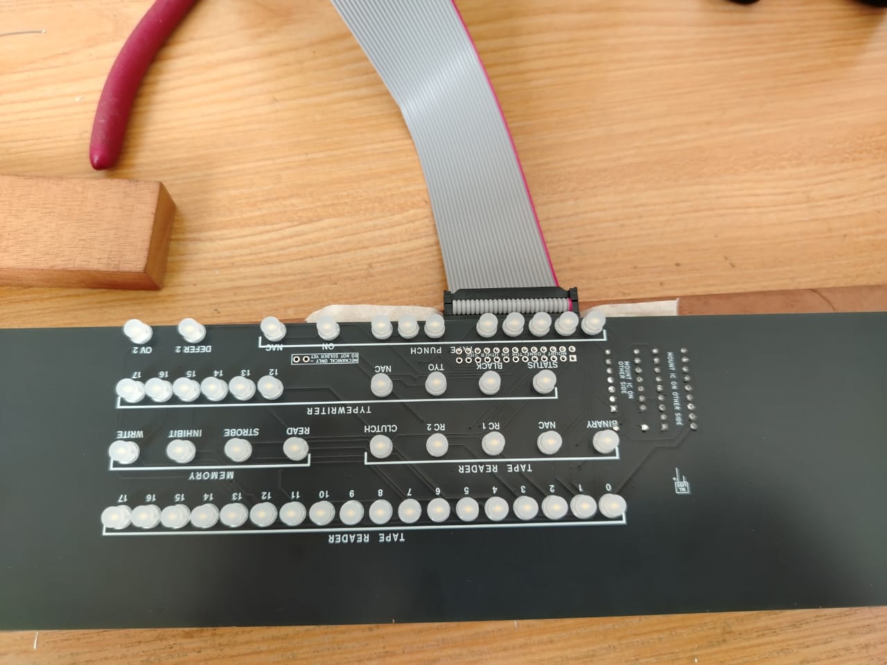 1. Put the LEDs into the front of the I/O PCB (Ref.#Q). They do NOT need LED spacers, as opposed to the main PDP-1 front panel.
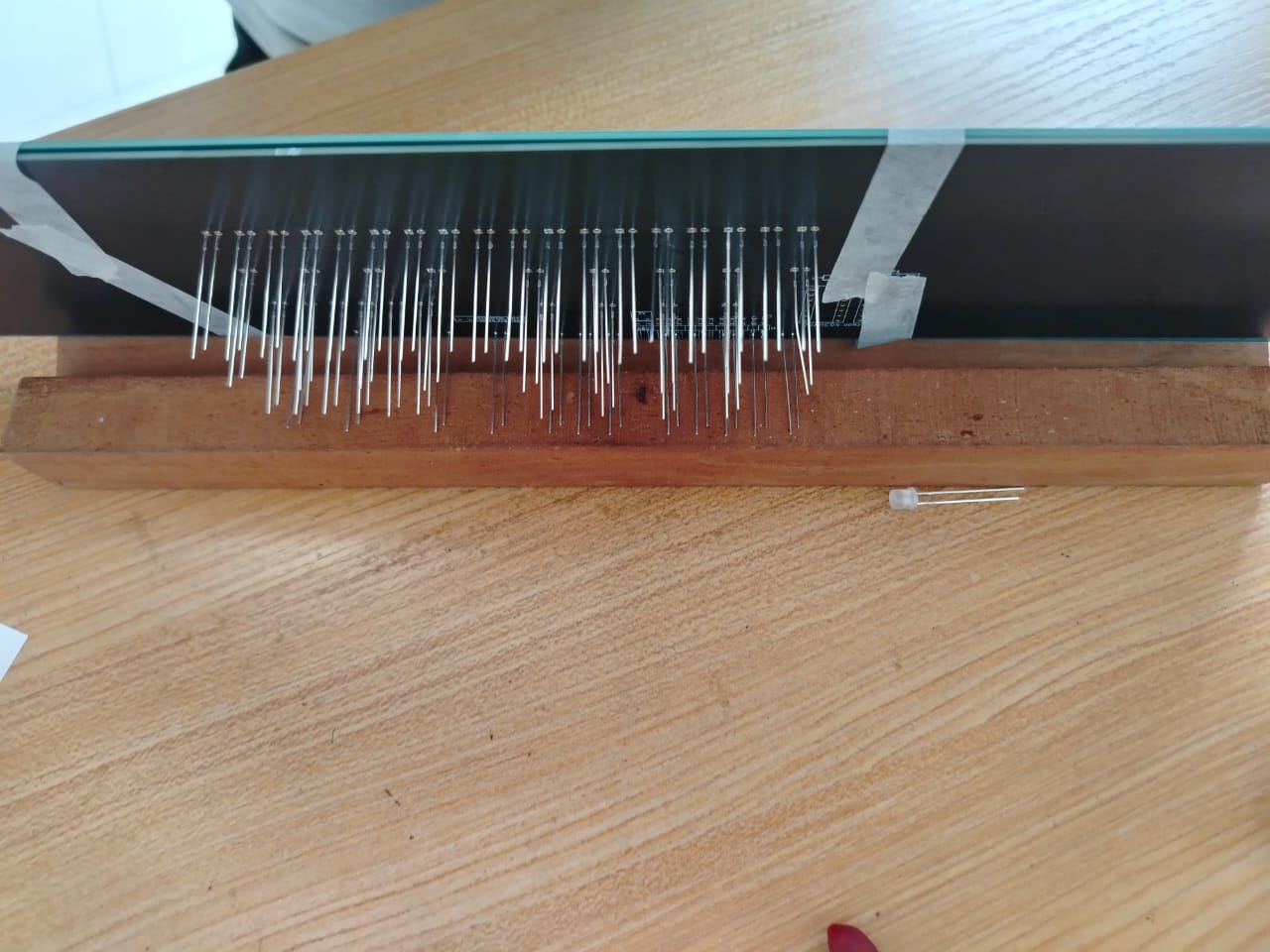 2. Put the IO cover panel on top so you are sure the LEDs fit through the cover panel, flip over, and solder up the LEDs. One pin first, so you can correct any LEDs that do not end up flush. Then the other pin.
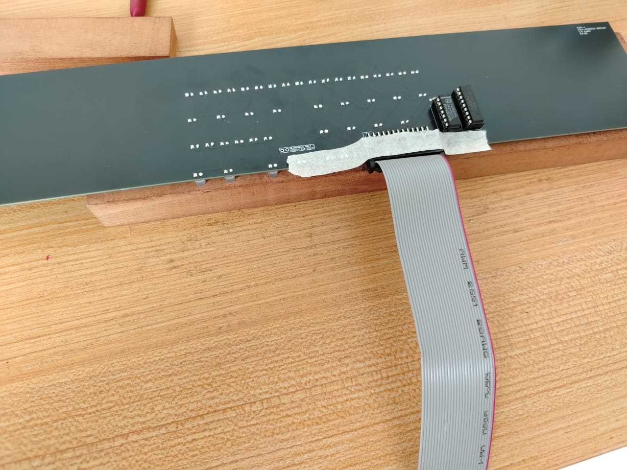 3. Add the angled pin header. It is a good idea to do this with the ribbon cable connector inserted, at least for the first few pins. So you know the angled connector is far enough from the PCB to fit into the connector.
 4. On the back of the PCB, solder the 2 IC sockets (mind the notch, match it with the footprint) and the diode. Insert the two chips in their sockets.
Rack version: build the Paper Tape Panel
Paper Tape panel: Overview

The PiDP-1 aims to be a close replica of the PDP-1 at Lawrence Livermore, which had an external, higher-speed tape reader. The DEC punch, however, was kept in the location now familiar from the PDP-1 at the Computer History Museum.
You're not forced to use USB sticks. Any paper tape file from SD card can be mounted too. But when you slot in a USB stick in either connector, that will be the paper tape 'mounted' on the PDP-1's reader/punch.
Until a real tape reader and punch become affordable again, USB paper tapes are the next-best solution to experience how it feels to operate a PDP-1. Much better than 'clinically' mounting image files from some tape directory...
Solder up the Paper Tape panel parts
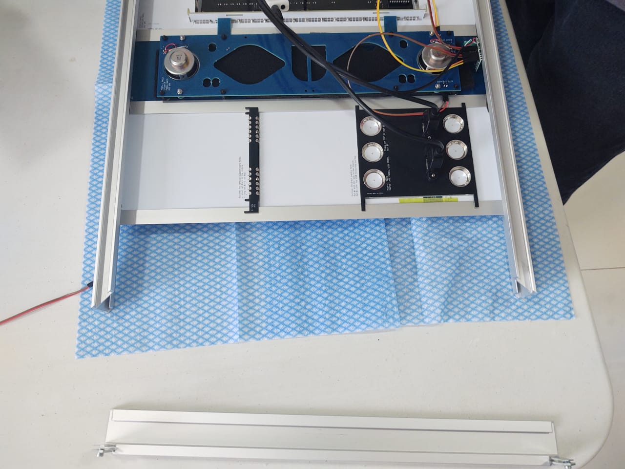
The Paper Tape Panel needs to be constructed from 3 layers of panels: white front, black spacer panel to give some depth. then a black panel to mount the USB ports on.
As electronics people, the idea is not to use glue, but solder to put these together.
The processs is best explained in pictures. As always, click to enlarge images. Note that all parts are facing down, and so their part numbers MUST be visible on the top right of each part as you build it together. Make sure to check that, so you do not put parts upside down or reversed!
1. Joining Layer 1 (white &s blue) and Layer 2 (black):
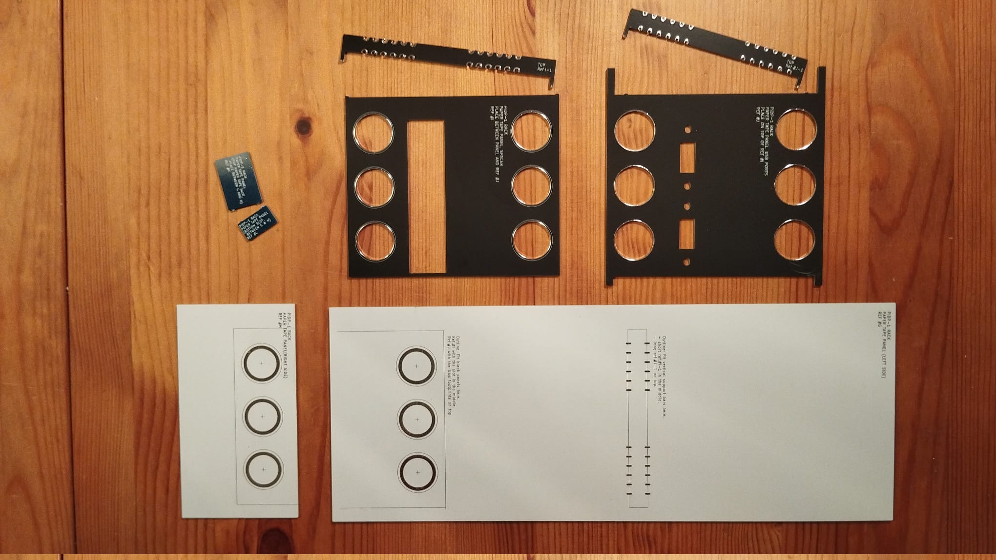 Break up parts #I and #J. Use a side cutter for a partial incision first, then break up by hand. It's not delicate or risky. No need to be neat either.
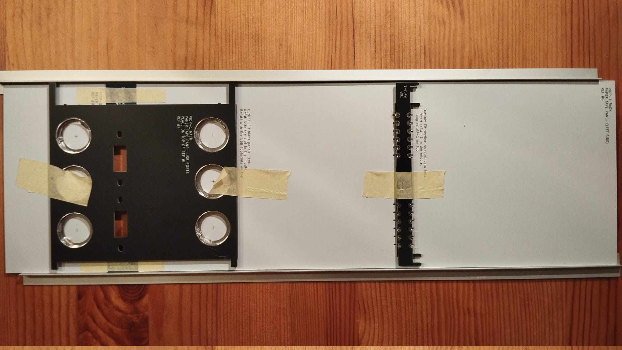
 Put the parts K and L between the aluminum profiles supplied in the kit, using them to neatly line everything up. Tape parts K and L to panels G and H, tightly against the aluminum guides for neatness. Make sure the tape does not enter the rectangular area indicated by the lines above/below it on the photo.
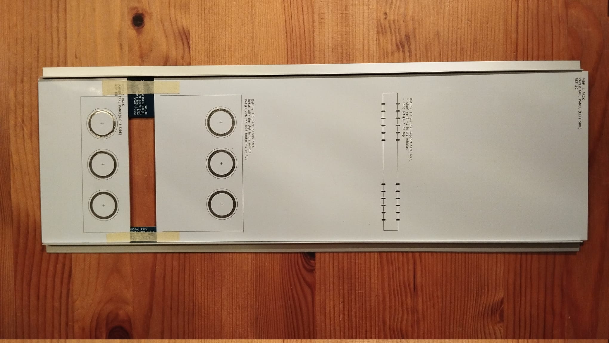
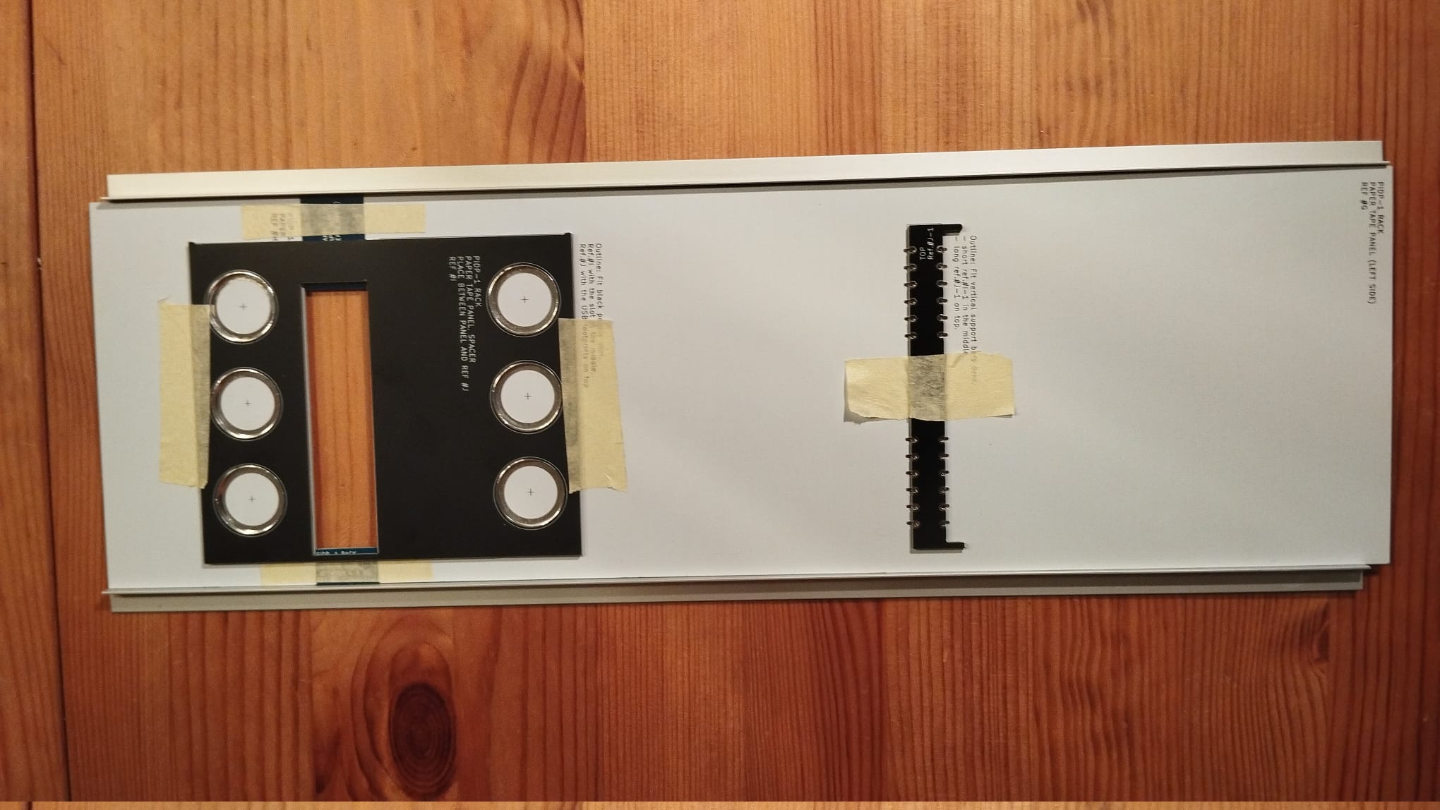 Very, very precisely place part I on the indicated place, and make sure it is exactly aligned with the guidelines on the panel. Very exactly, this is one step where precision matters. Then tape it up and check after taping if it is still aligned precisely (note 1).
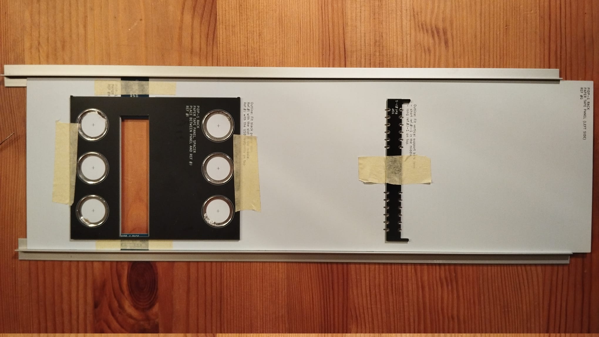 Do the same for the narrow part J-1 that you broke off from part J. It's the shorter of the two narrow parts. Note the text 'top' on it, it needs to be at the top. Here, you do not need super precision, it's an ugly construction part hidden from view. It simply helps to clip the panel into the metal strips above and below it on the panel, nothing more.
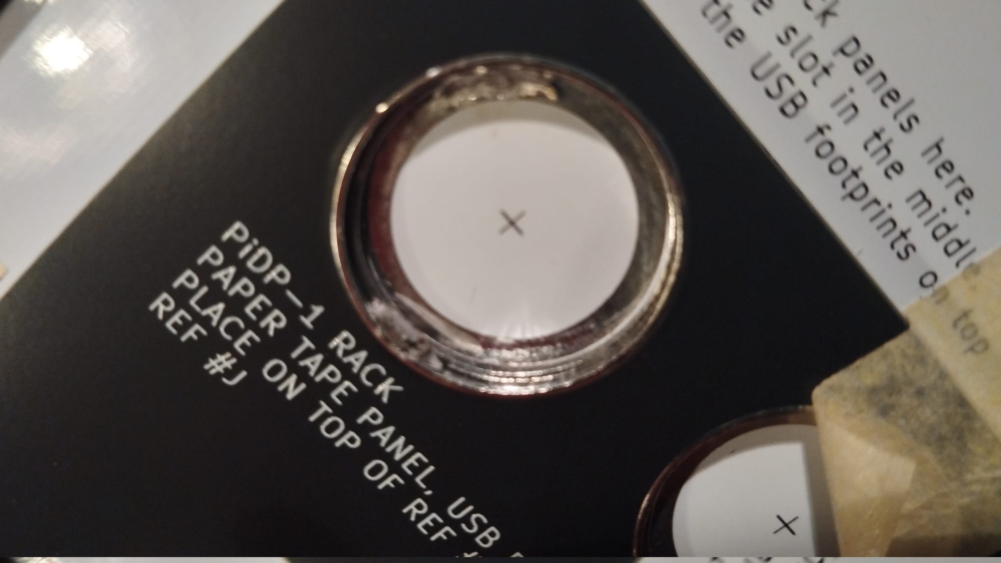
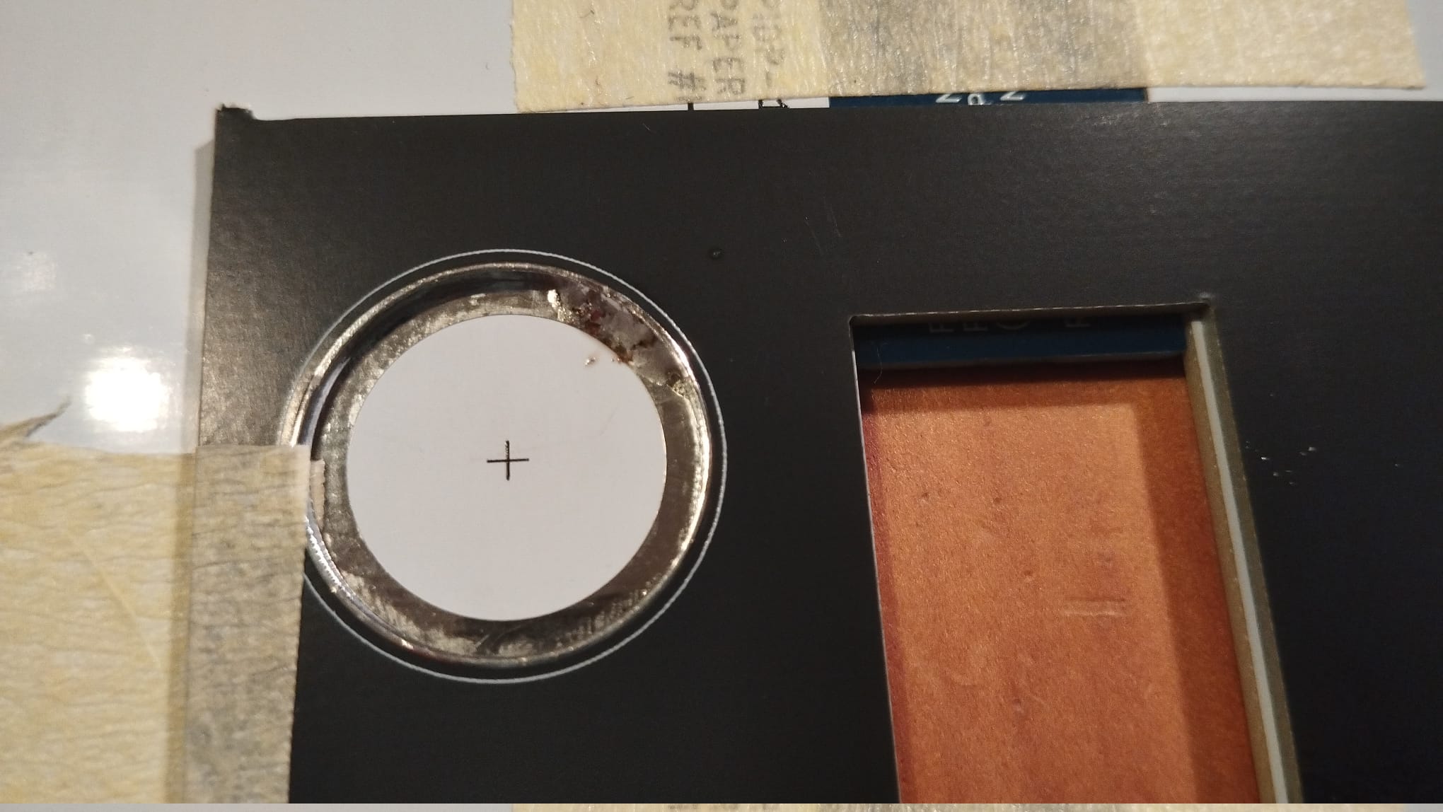 Close-up: Do a small solder blob in 4 of the circles to fix the black panel to the white panels. If alignment is good at the end of this section, you can fill up the whole circle with massive amounts of solder blobbing. But if not, you're still able to reheat & reseat to fix any misalignment. First go on with the next step - adding the second black panel.
Note 1: the best way to check precise alignment is easy. See how the gap between the white panels is slightly narrower than the slot in the black panel. Make sure the stripe of white you see on both edges is straight and symmetrical. That's sufficient to know you've done the alignment precisely.
At this stage, you have soldered on the first of the two black panels. The second, Ref.#J, comes up on top of that first one. The USB connectors will be mounted in this second black panel, and its positioning needs to be just as precise as the first one. To see why, look at Ref.J: you want to have the glossy metal 'U shape' aligned precisely for cosmetic reasons. It's highly visible (maybe we should have left off the glossy U shape, but it is there in the real machine, and we want this to be a close replica).
Now you know what the thing is you have to look out for, go ahead and solder the second black panel on top of the first one.
2. Mounting the 3rd layer: Panel #J.
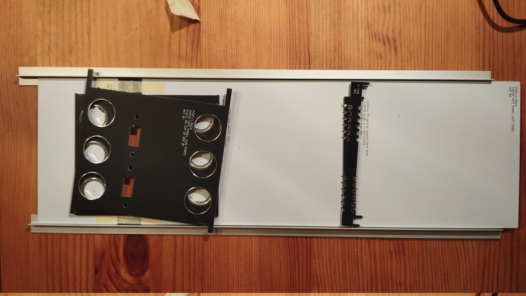 Here, roughly placed on the target location...
 ...now placed very precisely and fixed in place with tape. Solder up with 4 only small solder blobs, to the first black panel.
 Tip: solder black panel #J to black panel #I with a solder spot that is away from the solder spot that joins black panel #1 to the white panel. That makes it easier to fix misalignments if you need to.
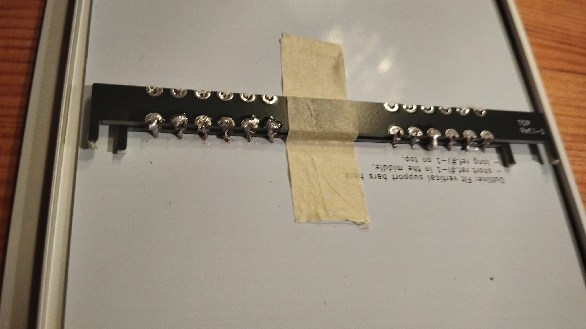 Also, put the second and longer break-off bar, I-1 on top of the first. Note the label 'TOP', and note that this part is taller than the first. That is because the aluminum profiles will be wedged between the white panel and the second black panel later on.
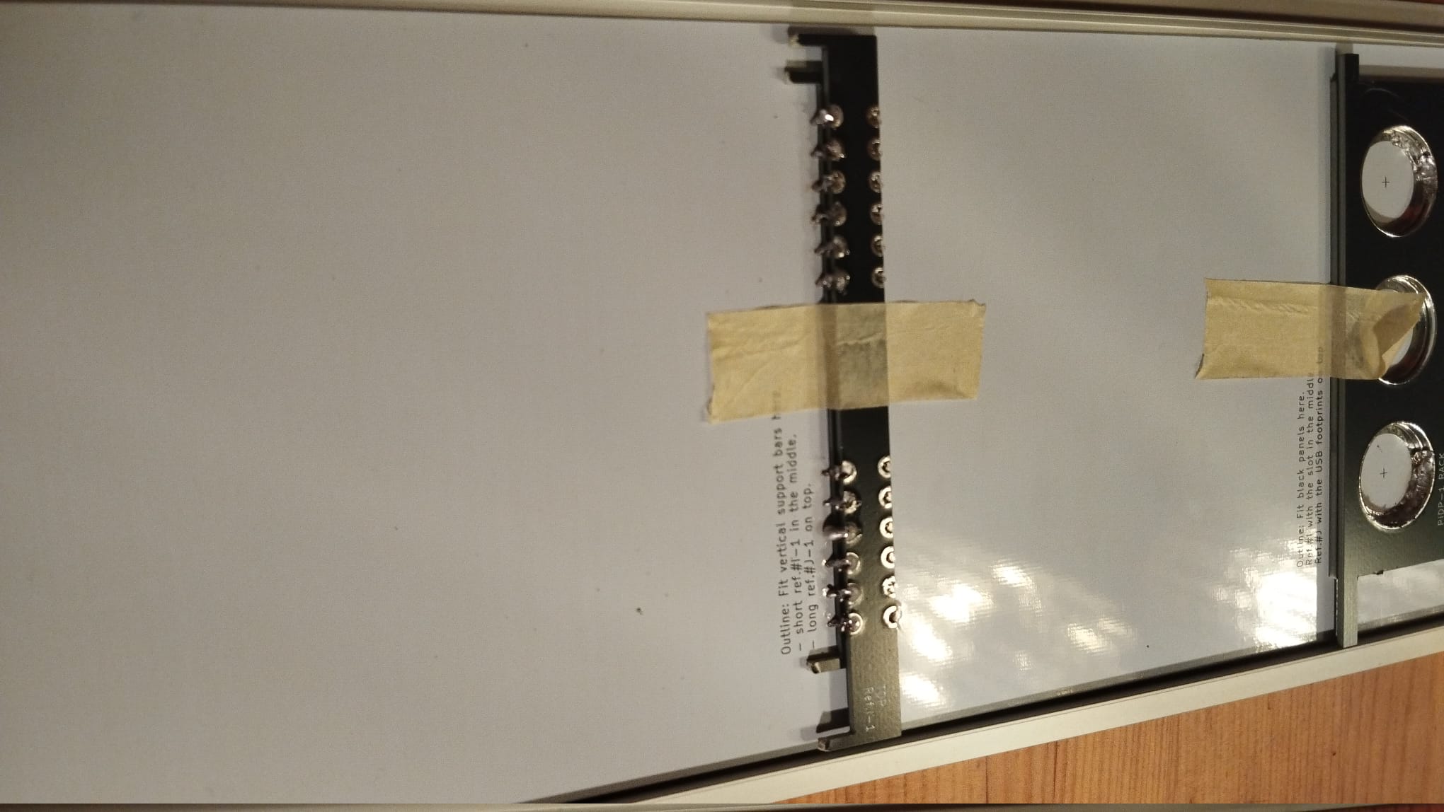 Just one more shot of how it all looks by now. Look from the front to see if everything looks good. If not, reheat & reseat. If it does, use lots of solder as if you were Mario the plumber to fill the solder circles!
Mount the USB connector cables
This does not need photos: Put two USB connector cables in to the Paper tape panel with the provided 2 screws per cable. The screws go in from the front. Align the USB connectors neatly before you tighten up the screws. They have some flexibility in positioning.
Fold down the cables coming out of the panel connectors with some force. They will need to make a sharp 90 degree turn to the bottom. You will insert the two USB cables into the Pi during the last construction step.
Rack version: build the Speaker Panel
Speaker Panel: Overview
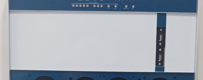
The panel's structure consists of the Speaker Frame (#N), mounted behind the actual Speaker Panel (#M) itself. The optional monitor can sit behind the two center holes in the panel, showing a combination of terminal, paper tape visualisation, and Type 30 display – set up according to your preferences.
The monitor slot was designed to take pretty much any 7 inch display stiing in between the Panel and the Frame. But depending on your particular display's connector placement, you do need to take out one of the 8 M2.5 spacers to allow room for the bulky HDMI cable. Just leave the bolt on the front, and put the nut on it instead of the nylon M2.5 speaker. That gives ample room to the HDMI cable, wherever it may be located on your particular display.
Build the Speaker Frame
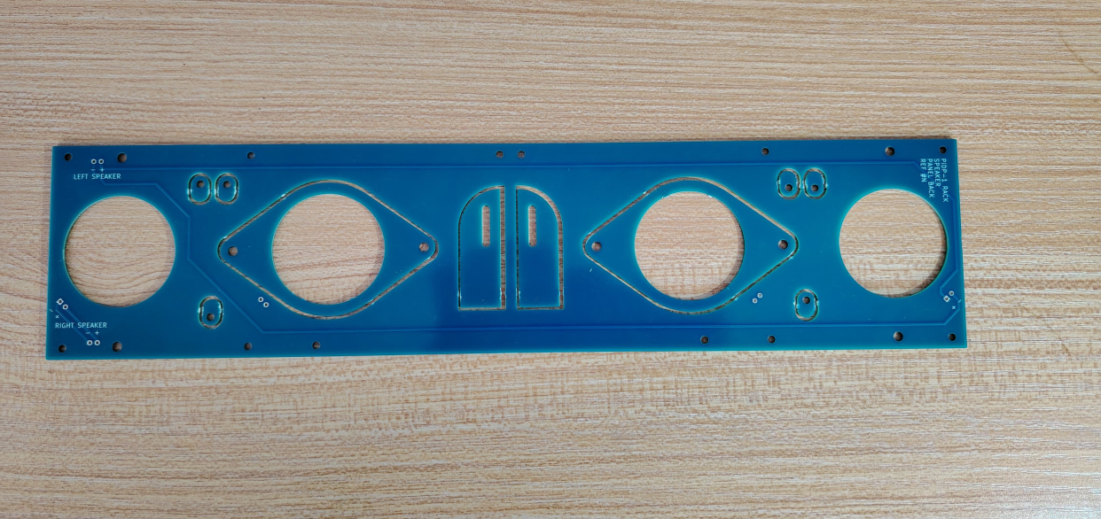 From the Speaker Frame (Ref.#N), press out the 2 speaker mounts, the 2 long tabs and the 6 little oval tabs.
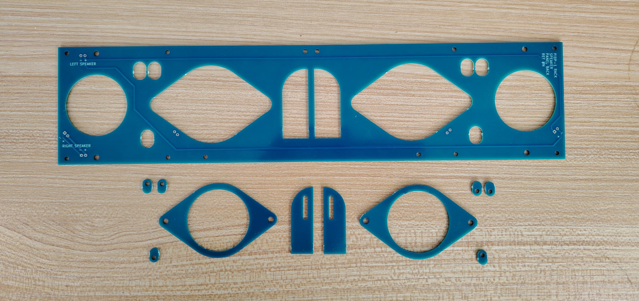 The press out parts laid apart. These will become construction parts.
The two 'saloon door' tabs will be used as latches to lock the speaker panel into the operator panel below once you put everything in the alunimum frame.
The 6 little oval tabs proved unnecessary - you can ignore them.
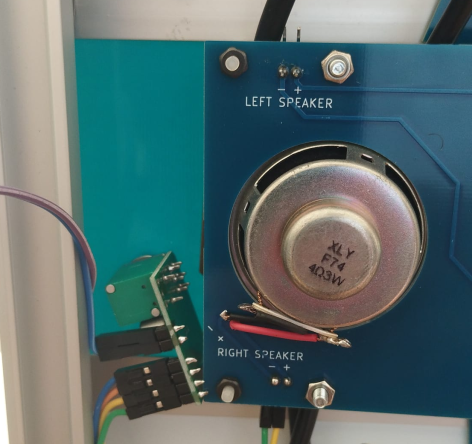
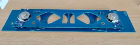
Build the 2 speakers onto the Speaker Frame:
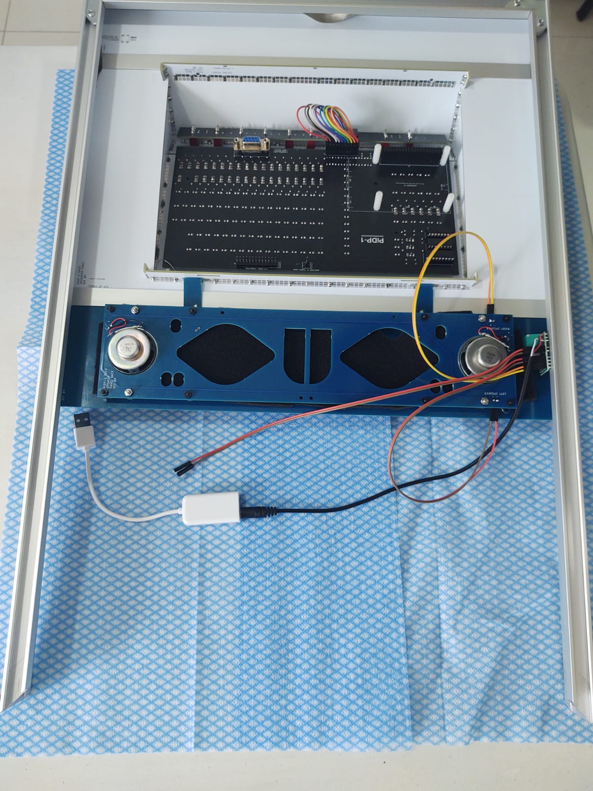
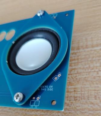 Put the speaker in through the front of the Speaker Frame, put the press-out speaker mount on top, fix with a M3 nut/bolt
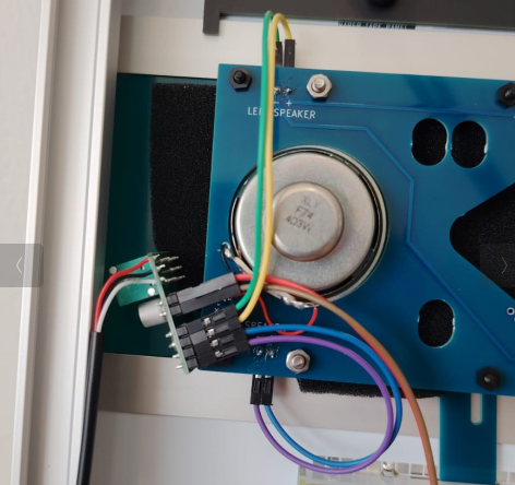
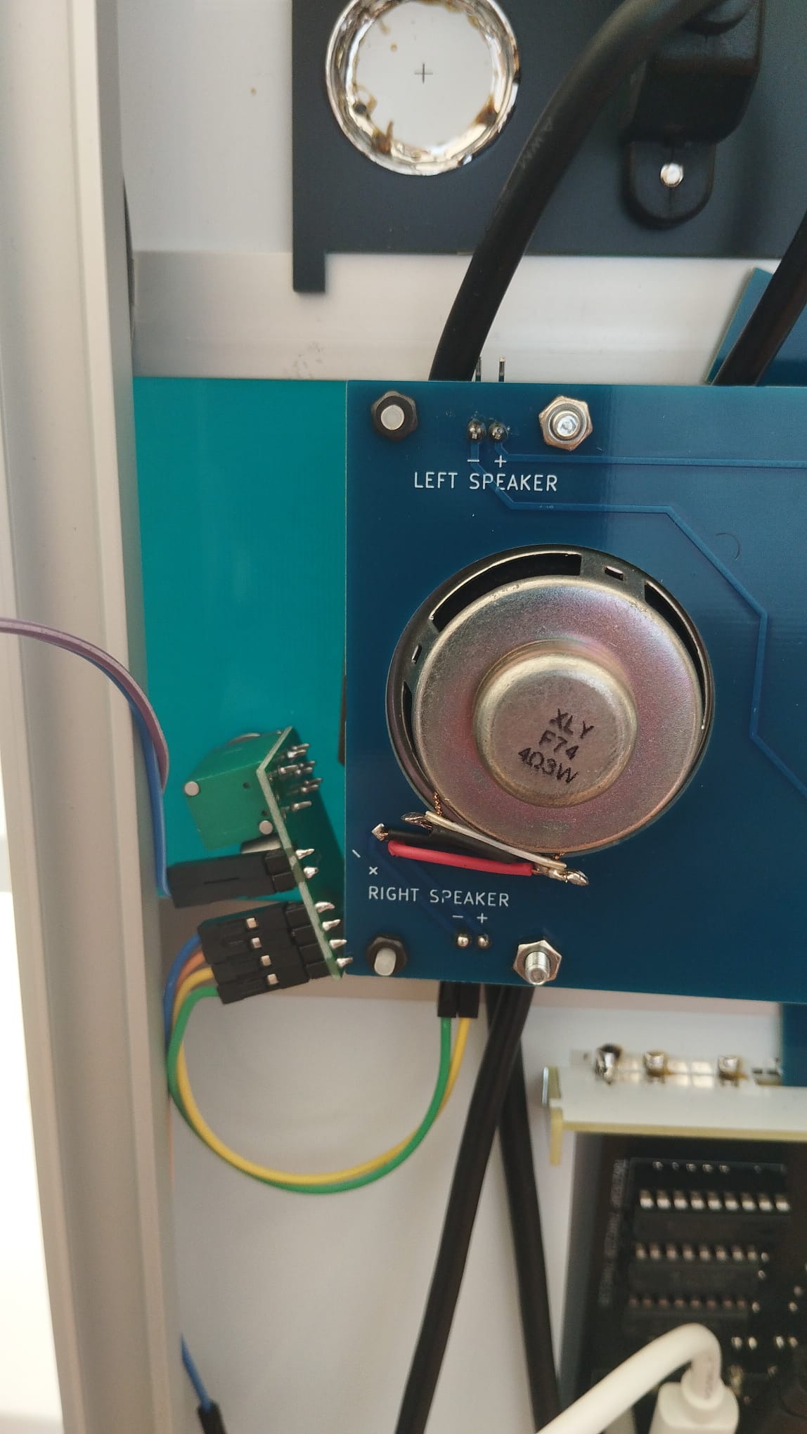
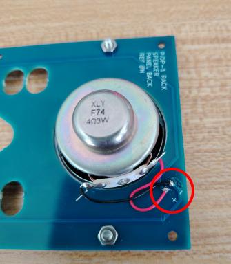 Wire each speaker's solder tabs to the indicated solder holes on the Speaker Frame, using the red/black wire
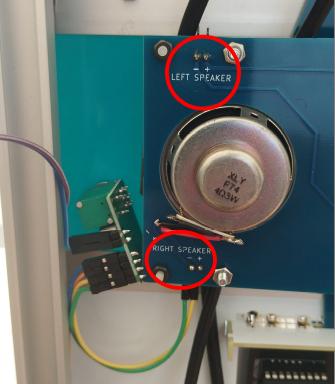 Solder two angled 2*1 pin headers to the speaker connectors on the speaker frame, see red circles in photo.
Later on in the process, use the 4 10cm F/F 'rainbow wire' with Dupont connectors, to connect them with the amplifier.
Solder two angled 2*1 pin headers to the speaker connectors on the speaker frame, see red circles in photo.
Later on in the process, use the 4 10cm F/F 'rainbow wire' with Dupont connectors, to connect them with the amplifier.
Mount the Speaker Frame on the Speaker Panel (#M)
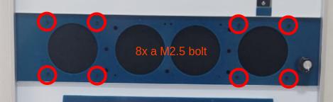
Insert 8 M2.5 bolts from the front of the Speaker Panel (#M)
To the right: your photographer forgot about the black speaker cover foam, please don't make the same mistake :-)
1. On the inside of the Speaker panel, screw in the 8 nylon M2.5 hex spacers.
2. For the middle 2 hex spacers on the bottom row, before you mount the hex spacer on the bolt, put on the little "saloon door" tabs that you pressed out of the speaker frame earlier on. They will act as latches to lock speaker panel and operator panel later on. You can see them in the photo. Place them with the rounded corner facing to the side of the frame - the same way they were positioned in the press-out.
3. ONLY if you plan to mount a 7 inch HDMI display: put an additional hex spacer on each of these 8, to give extra height for the display
4. Put the Speaker Frame on the hex spacers; put 8 M2.8 nuts behind the Frame
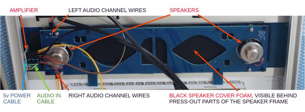
Mount the amplifier on the Speaker Panel
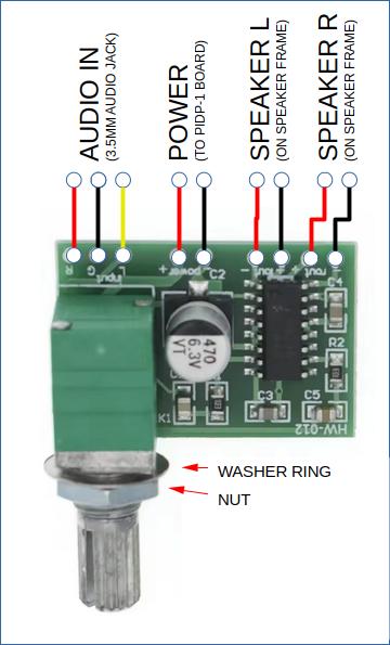
Mount the little amplifier board by putting the volume knob (with the washer ring provided with the amplifier board) through the mount hole at the very bottom right of the speaker panel (#M); tighten with the nut provided with the amplifier board, and then push the volume cap onto the knob.Cut off parts of the provided red-and-black speaker wire to connect the amplifier to the speakers, and to the provided 3.5mm audio jack cable as follows:
 Add pin headers to the leftmost 6 solder pads (for the speakers and the 5V power).
Use the 4 10cm F/F 'rainbow wire' with Dupont connectors, to connect the amplifier to the Speaker Frame's pin headers for both speakers.
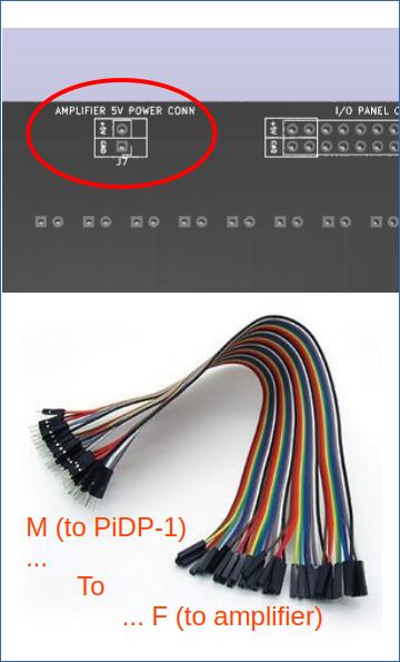 Connect the 5V power connector to the PiDP-1 PCB. Use the 2 strands of 30cm M/F rainbow wires. 5V to 5V, GND to GND, careful here!
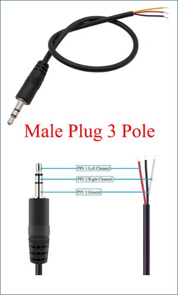 Solder the audio jack cable straight on the remaining three pins of the amplifier.
Just in case the colours on your cable deviate from ours: the pin order on the photo of the PCB is Left (red), Ground (black), Right (yellow). Check the cable pinout if your colours do not match the photo!
 Mount the amplifier on the Speaker Panel as shown. The provided ring goes on the back of the panel, the nut on the front. Now, push on the volume knob
Mount the speaker foam
First, on the back of the Speaker Panel itself (ref.#M ) use some glue (it does not matter too much what type) to cover the 4 ‘speaker holes’ with the provided speaker foam. Of course, if you use a HDMI monitor behind the center 2 holes, do not cover these two!Rack version: Construct the aluminum frame
How we got to make a custom aluminum rack
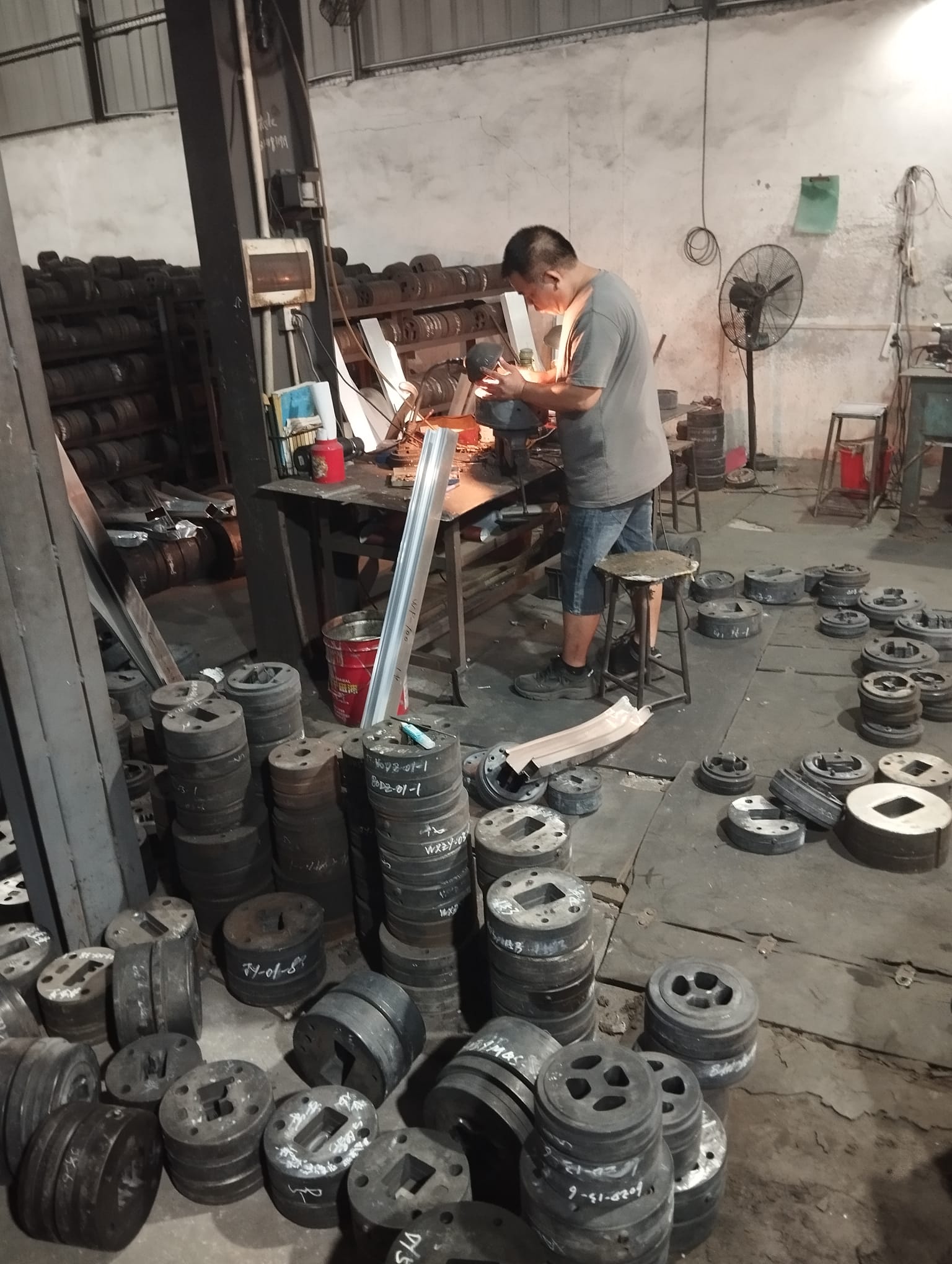 Making molds is skilled work, done by hand. The mold maker told us he'd just a custom mold for us, no worries... thank you!
So we were rather grateful for the help we got - a custom profile was certainly not a commercially relevant job, giving the tiny quantities we needed.
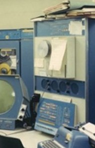
On the right, the machine used to push the hot aluminum through the mold. It felt embarrassing to only order a few hundred meters of these parts in a factory more used to making hundreds of miles of aluminum profiles. But they were nice enough to sneak our mold in on a quiet day.
So, that's why we have the frame as we wanted it!
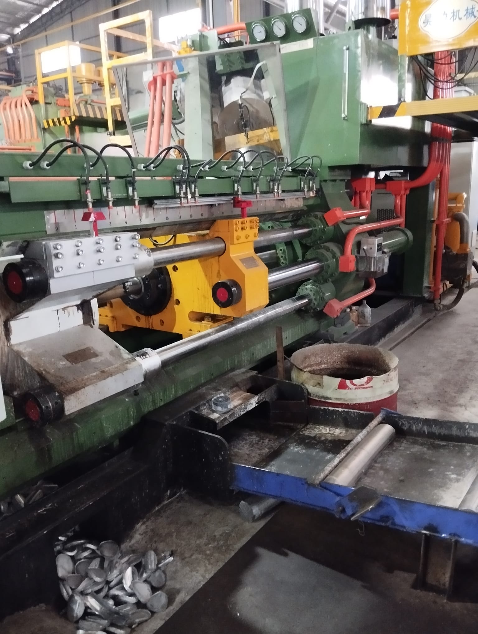 Click the picture for a short movie of the machine...
Use three of the four aluminum profile to construct a U-shape
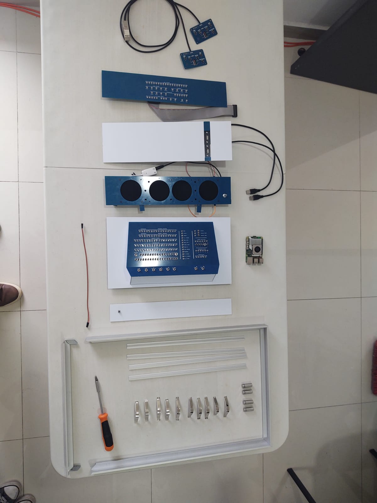
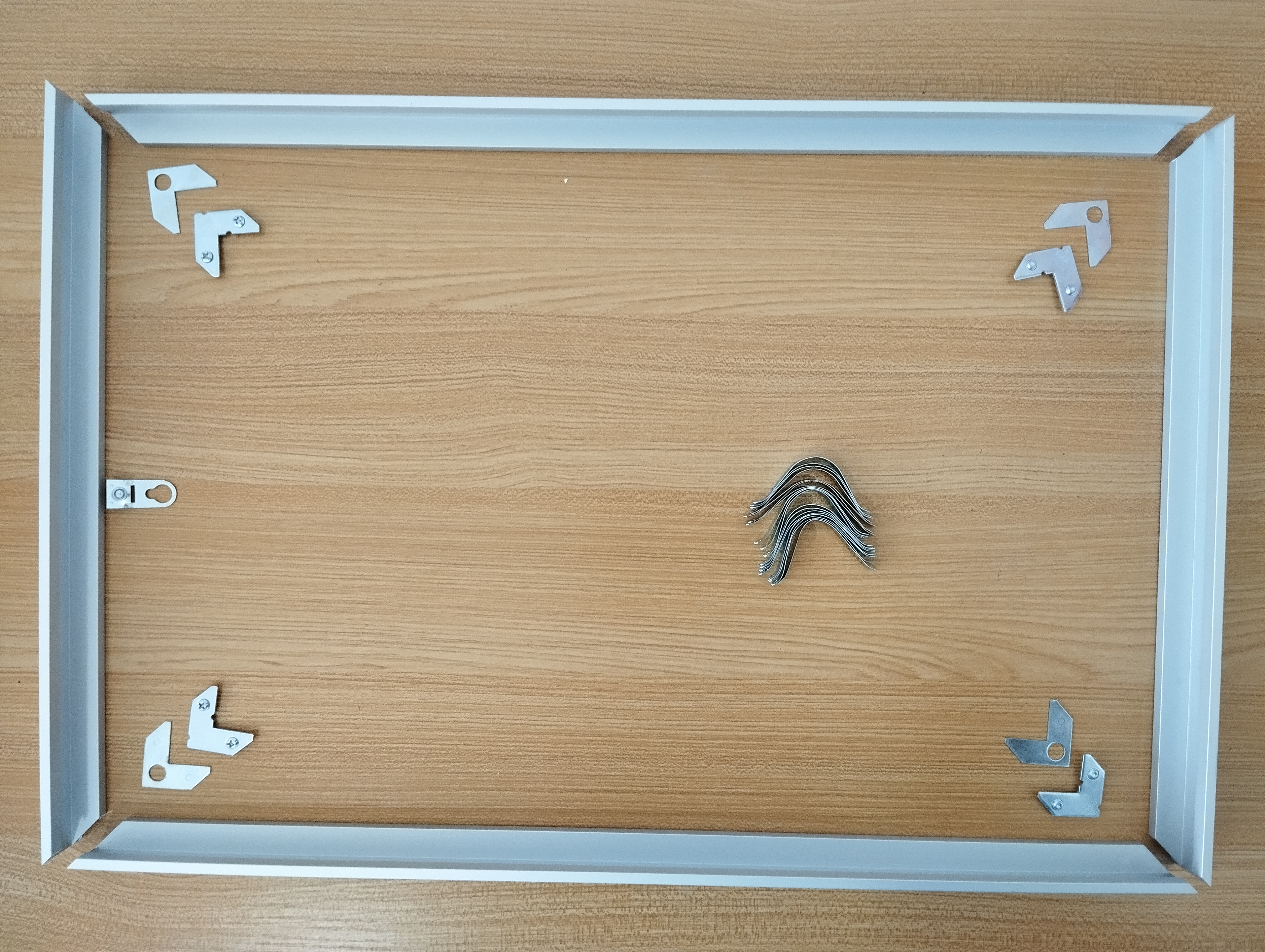 The components of the frame itself.
Not shown are the 4 stand-offs that can be mounted to the back of the profiles, and the 4 T-bar separators that go between each of the panels.
The components of the frame itself.
Not shown are the 4 stand-offs that can be mounted to the back of the profiles, and the 4 T-bar separators that go between each of the panels.
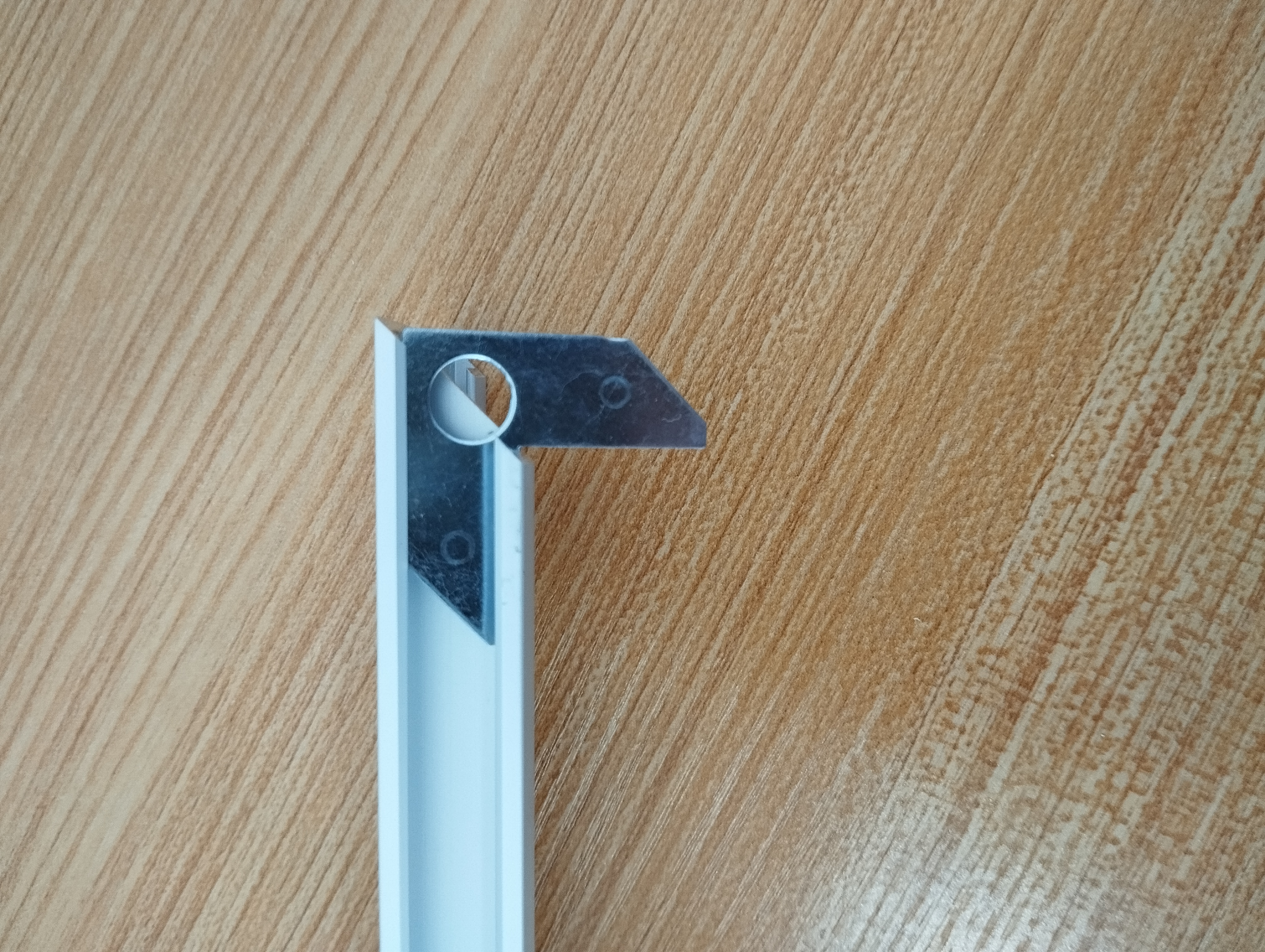 To join two of the aluminum profiles, insert the first corner part...
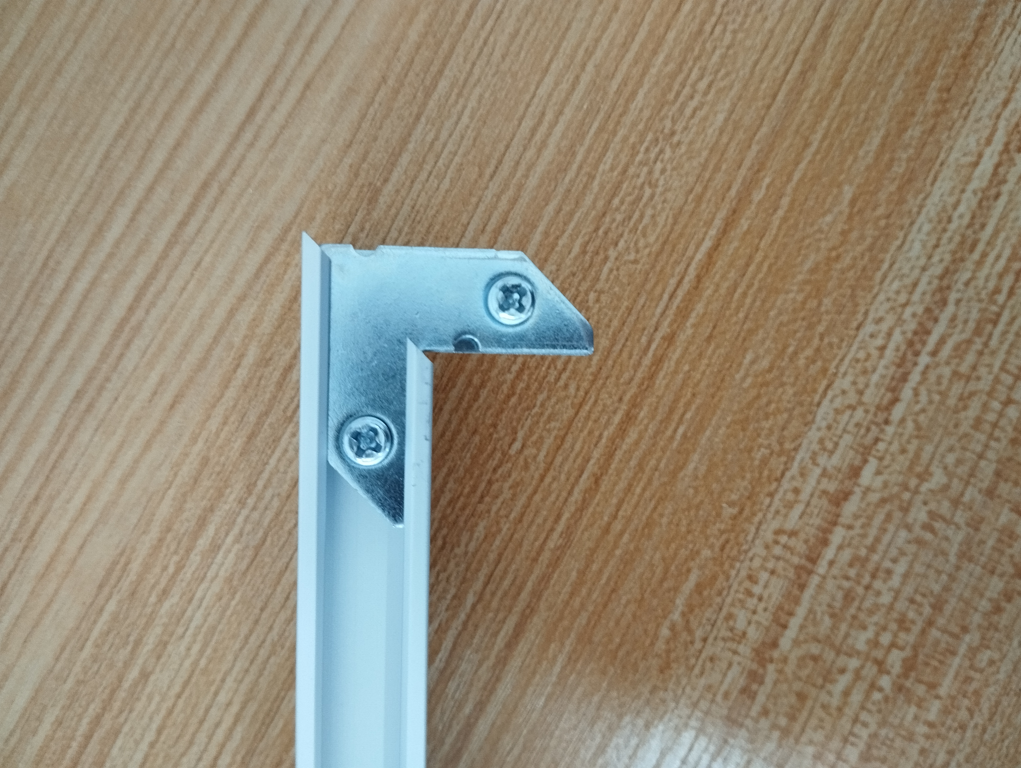 ...then the second one with the tightening screws. Tighten the screws to fix the connection...
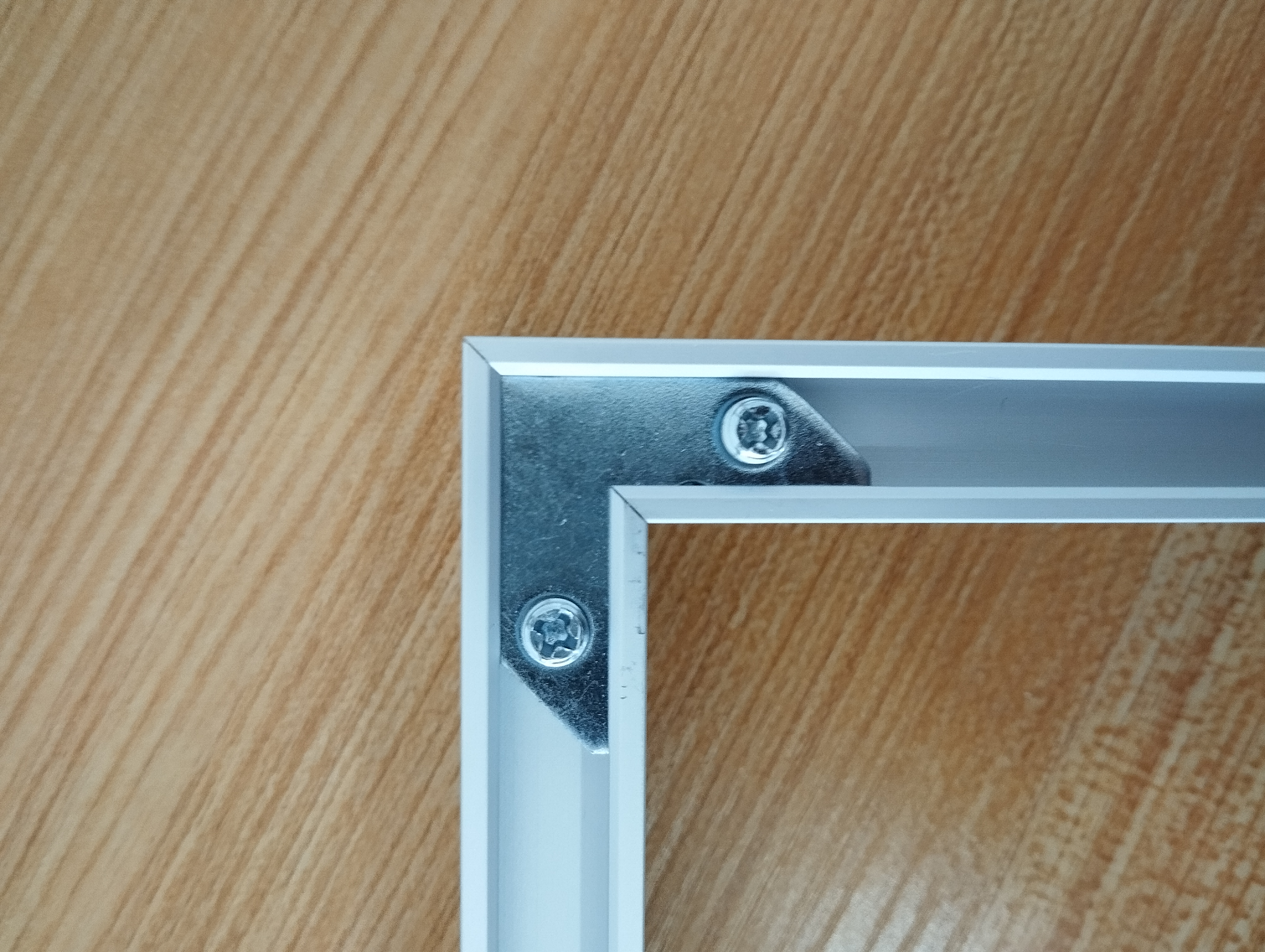 ...Connection made.
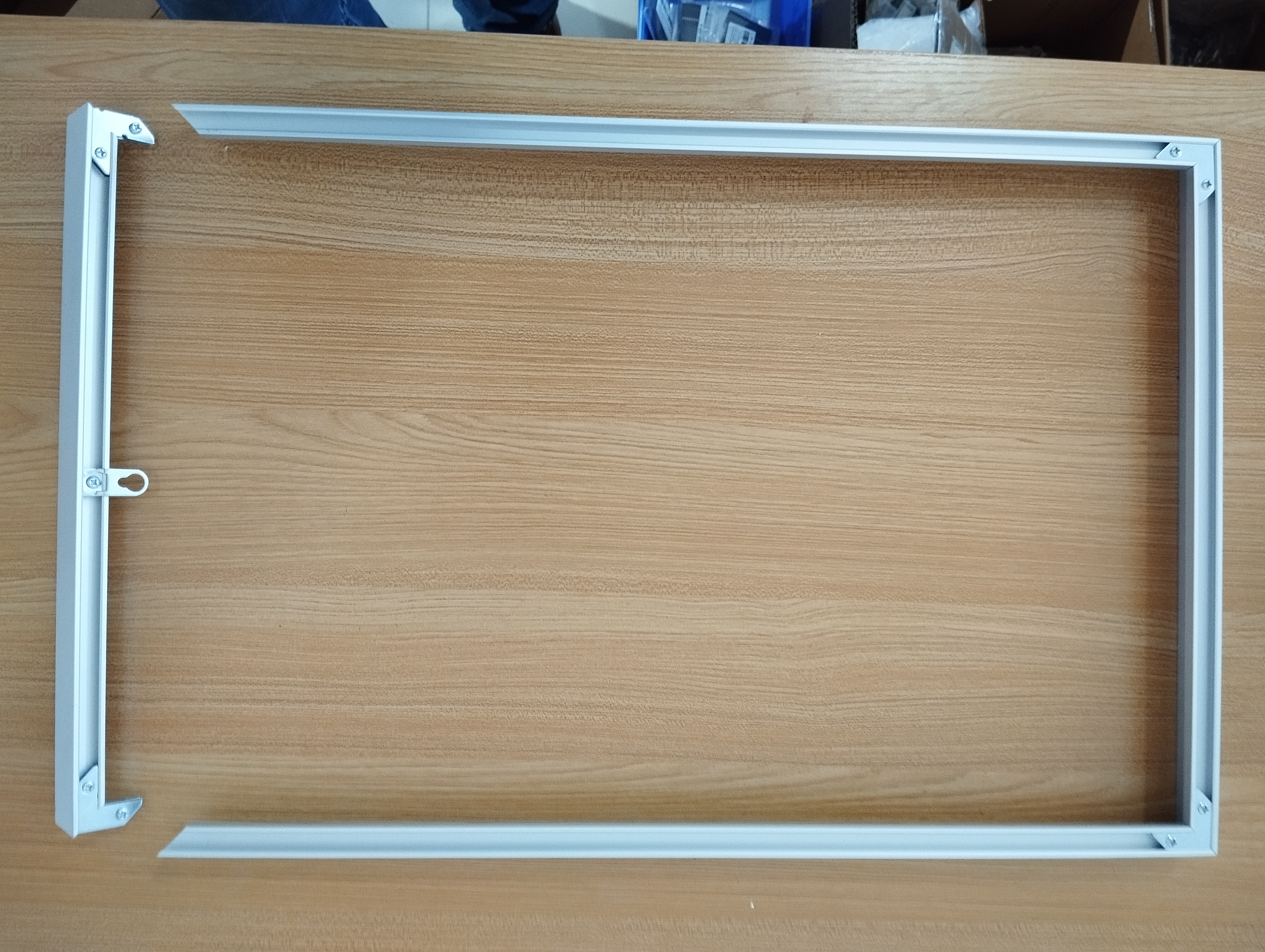 For the moment, leave the top of the frame off. We first need to stack up the panels in it.
Slide in each of the panels
 An overview of all the parts. Note the U-springs inside the aluminum frame, used for tightening each panel to the sides inside of the frame.
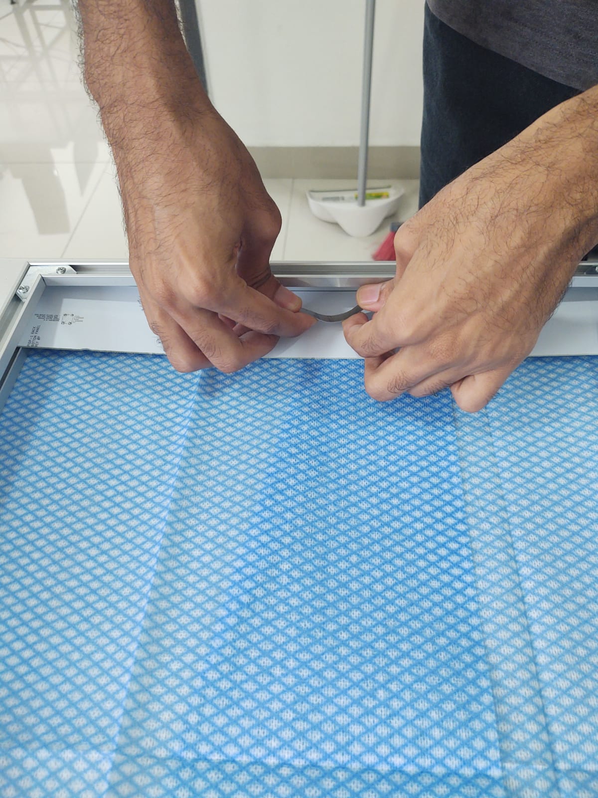 Slide in the bottom panel, fix with one or two U-springs at the bottom.
Put in the first of the T-profile aluminum separator strips on its top. Let U-springs press on the left and right of the strip (not the panel itself) to hold both the strip and the bottom panel in place.
 Then, slide in the Operator Panel (the one with the front panel on it). For this panel, use two U-springs on the left and two on the right. It needs to be firmly pressed in place for when you operate the front panel switches!
 Add another T-profile separator strip, then the Speaker Panel. Use more U-springs
 The Paper Tape Panel is inserted next. Plus another T-profile separator
 The I/O panel comes last. Mind: the T-profile separator sits betweenits front panel and its actual circuit board!

 This is optional. If you want more depth behind the frame, 4 of these frame spacers are included. You need them when you opt to put in the USB connectors, even more when you add the optional 7 inch display. Otherwise, you might leave them off.
 These spacers come with a nut, which you slide into the frame's side profiles, and a spacer cap, which you screw tight once you've slid the combination to its desired spot. Logically, you put one close to each of the four corners of the frame.
 Screw on the top of the frame.
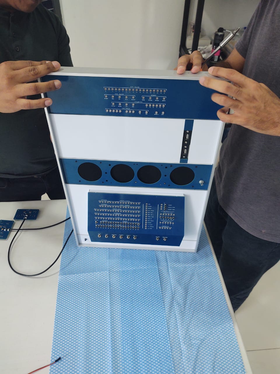
 You're ao close to being done.
But not quite :-)
Badges are still missing on the front, and you still need to connect the cables on the back
Wiring up & applying the PDP-1/DEC badges:
- I/O panel: the ribbon cable needs to to the top of the PiDP-1 main PCB.
- Paper Tape Panel: the two USB cables need to go from the to the USB ports of the Raspberry Pi.
- Speaker Panel:
- the 5V/GND wires need to go into the female pin header at the top of the PiDP-1 main PCB.
- the 3.5mm audio jack needs to be plugged in to the USB audio dongle, which needs to be plugged into the Pi.
DEC did not always do this, and the position they used varied as well. You should at least care about placing it nicely straight though. To guarantee that, place some rectangular object flush against the aluminum separator bar above the panel, pre-glue the badge, and push it flush against this object. Again, the precise positioning is not really defined!
If you are not using the little Pi 5 power button on the bottom panel, you can put the "dec" badge there to cover it up.
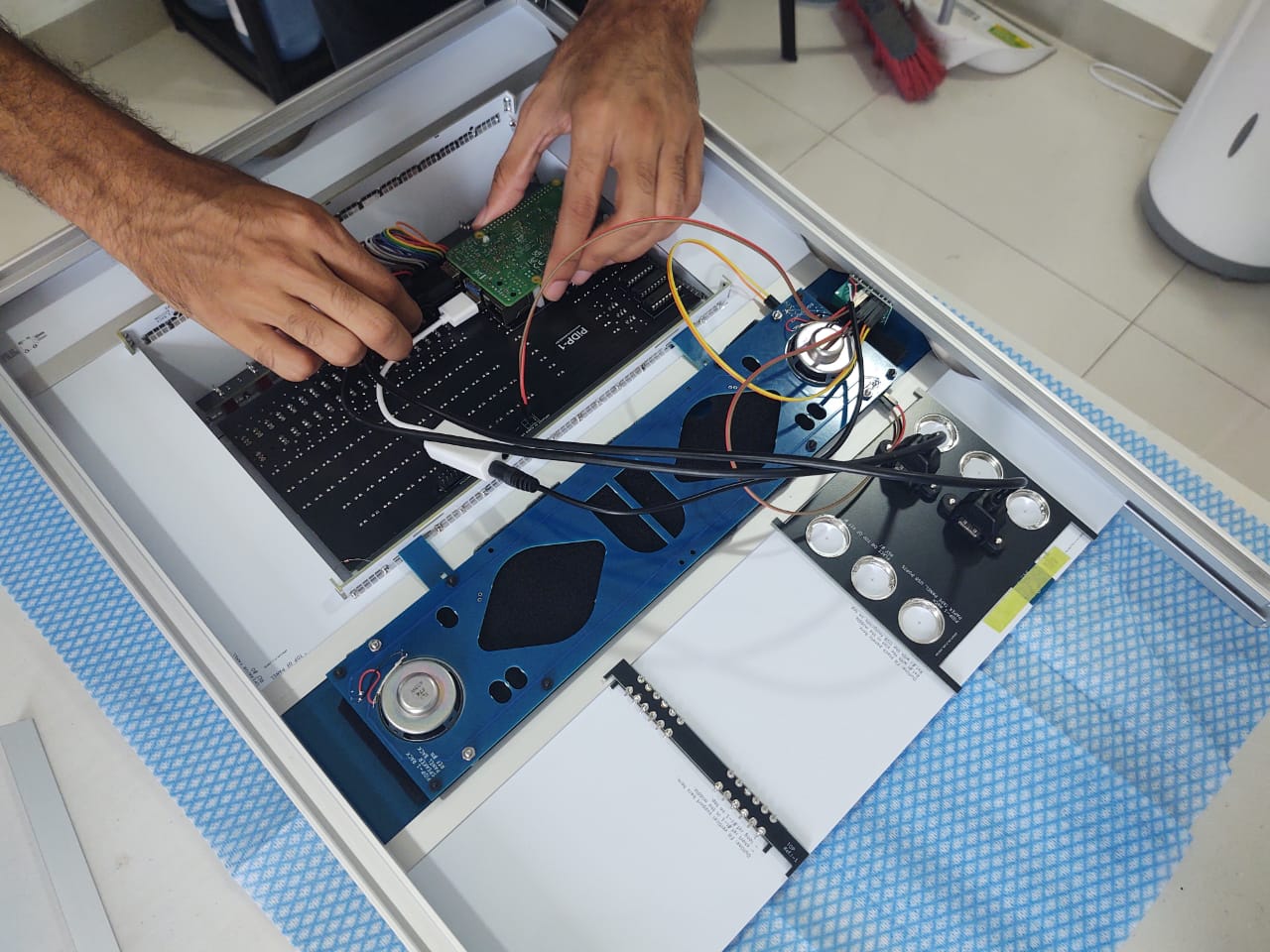
Wiring the panels to the PiDP-1 main PCB
Use the 30cm ribbon cable to connect the I/O panel to the connector at the top of the main PCBInsert the USB audio dongle into the Pi, plug in the audio jack from the speaker panel
Insert the two USB connector cables from the paper tape panel into the Pi
Optional, if you have a Pi 5: add a wire from the bottom panel's tact switch to the power switch footprint of the Pi 5
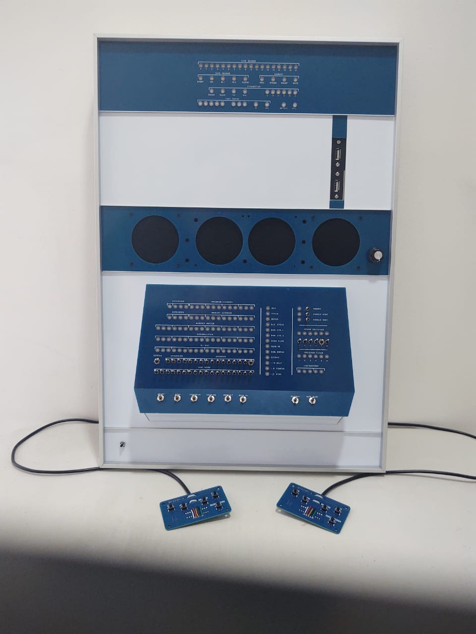
And you are done!
It was a lot of work - but we hope to placate you with the comment above: the 1959 version of the PDP-1 was even more work...
Please let us know of any feedback on this buiding instructions page. It was written in August 2025, so it is fairly new. And such instructions tend to improve in clarity from feedback. Thank you!