The PiDP Parts Tester
Always use the tester with the Raspberry Pi REMOVED! The Pi does not like 5V on its GPIO pins at all!
Starting from February 2026, we added a little component tester to the kits. If you should hit upon a problem, it comes in very handy, saving you and us time, debugging kits via email. As it turned out, the tester costs only $3 in parts - so it made sense to put it in the box. But do not think it is because we now allow ourselves to send you low quality parts... Please, we have our pride :-)
The PiDP Kits are pretty simple, so they are often built by first-time solderers without test equipment. Lots of switches = lots of solder points to miss, lots of LEDs = lots of risk that one is put in the wrong way round.
And the risk of a Bad Part is never zero. With a hundred LEDs, risk rises by an order of magnitude of 2... chances may be low, but not zero.
Actually, the tester is not really about finding Bad Parts. It is about eliminating that possibility when searching where a problem comes from. We actually recommend that you do not spend the time to test all parts before you build a PiDP kit! It is not worth the time; especially because you can use the tester on parts when they are already soldered in. Replacing a LED or switch is not that hard. But we know many people, nevertheless, like to test upfront. Admittedly, why not?
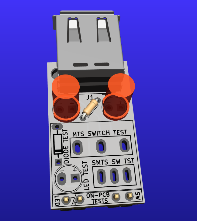
Soldered up
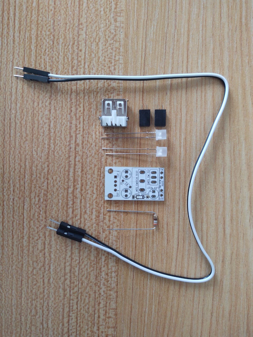
Tester parts
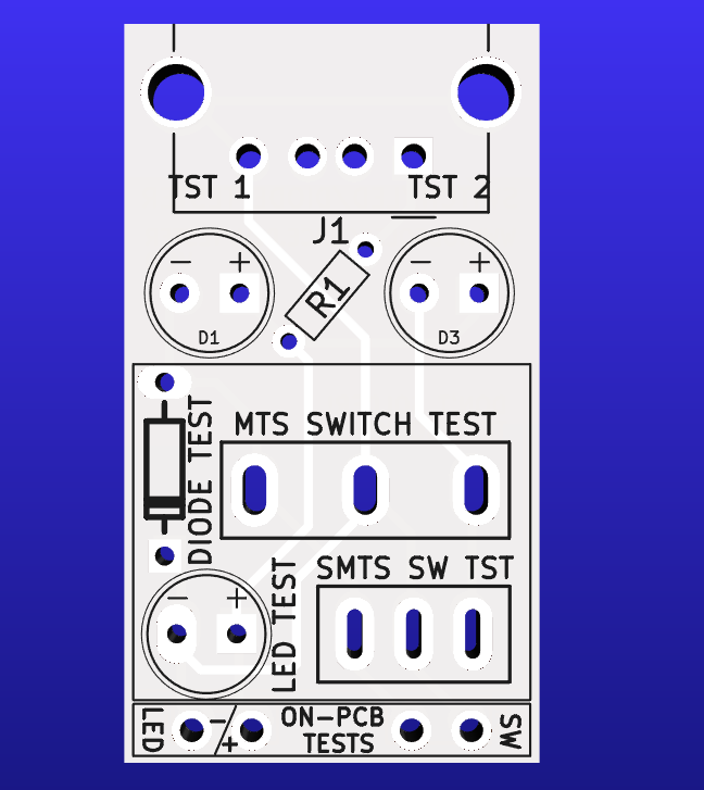
Front side of PCB
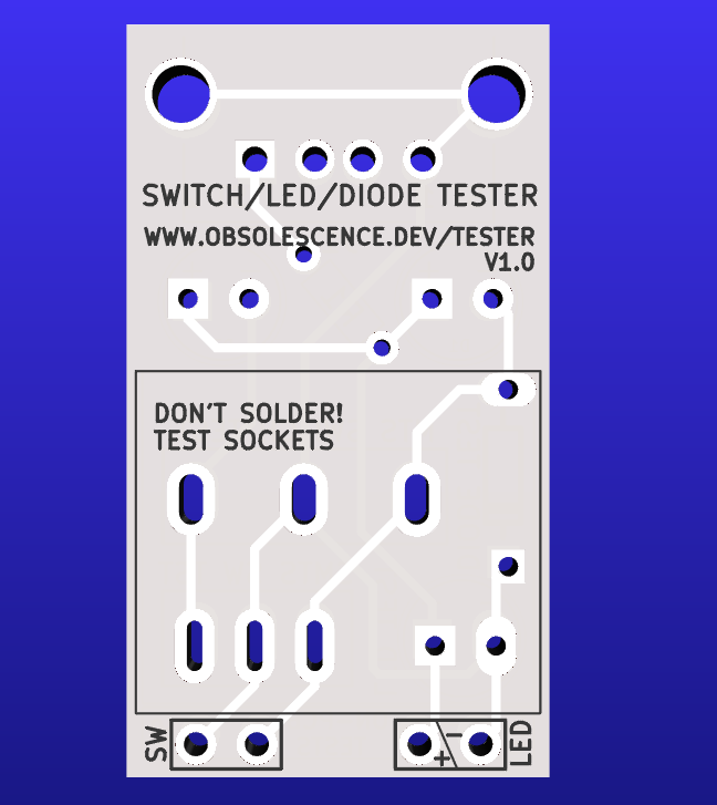
Back side of PCB
We hope you'll forgive us for keeping the tester very simple. What it does will be sufficient. You can use it to test:
- LEDS and diodes: do they work at all? Put in with the right polarity?
- Switches: do they make contact, in the up and down position?
- As a basic continuity tester: is there a connection between two points, yes-or-no?
Always use the tester with the Raspberry Pi REMOVED! The Pi does not like 5V on its GPIO pins at all!
Building the Tester
Put the USB connector on the top, and the two female pin headers on the back. See the pictures above. Put the resistor (any value between 200 and 2K ohm, does not matter) in-between the top two LEDs (type does not matter either). Make sure to get the polarity right on the LEDs though. Plus pin is the long wire on the LED. do not solder the other footprints, as per the warning on the PCB!
Keep in mind that a footprint makes poor contact without solder, so you might have to wiggle the parts a bit. This is especially true for switches!
Testing LEDs:
Parts test: put the LED in the LED TEST footprint. It will light up when inserted with the right polarity.
In-circuit test: put the two test wires into the ON-PCB LED header at the bottom of the Tester PCB. Mark which wire is the + one, connect it to the + pin of a LED on the PCB; the other wire on to its - pin. The LED should light up.
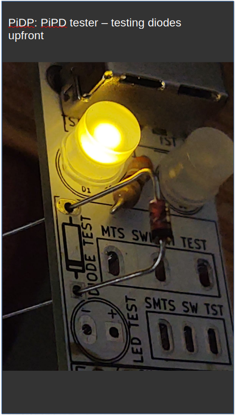
Testing diodes:
Similar to testing an LED.
Parts test: there is a DIODE TEST footprint to put a diode in. Put it in with the right polarity, and the upper left LED will light up. The other way around, not.
It is actually easier to test all the diodes with the test wires, see the right-hand video.
In-circuit test, do that as per the description on the LED test, the upper-left LED will light up when the diode is tested one way, and stay dark with the test wires held against the dode the other way.
Testing switches:
There are footprints for the small PiDP-1 switches, and for the larger 'regular' PiDP switches.
Parts test: with the switch set to UP, one test led lights up, with the switch pushed to DOWN, the other one should light up. One of the two LEDs must be on. Unless, of course, you have a three-position switch with UP-MIDDLE-DOWN! Please keep in mind the comment above: footprints without solder make for bad contacts. You'll need to wobble the switch in its footprint, and you should expect the test LEDs to flicker. It does not matter for testing basic switch functioning.
In-circuit test: connect the test wires to the lower-right pin header, SW TEST, at the bottom of the Tester PCB. One wire is held against the middle pin of a switch on the PCB, the other on either the top or bottom pin. If the switch is pushed down, there must be contact between upper and middle pins, if the switch is pushed up, there must be contact between lower and middle pins.
Testing for continuity or shorts:
In-circuit testing: connect the test wires to the lower-right pin header, SW TEST. Put the wire tips on two solder points. If a TEST LED lights up, you have continuity, otherwise, not.
This is especially handy if you have the drawing of the circuit board layout, where you can check how the traces on the board go from solder pin to solder pin, all the way back to the driver chips and the Pi's GPIO. For this, you can use the PiDP Kicad project files (it lets you right-click any trace and select Inspection->Highlight trace. But if you don't want to install the Kicad program, you can also use the drawings below.
PiDP-1 Kicad project
PiDP-8 Kicad project
PiDP-10 Kicad project
PiDP-11 Kicad project
PiDP-1 PCB layout
PiDP-8 PCB layout
PiDP-10 PCB layout
PiDP-11 PCB layout