Building Instructions for the PiDP-1 Kit
Building the Rack
Building the PiDP-1 should take about 20 minutes to make the case, then about 4 hours soldering up the PCB boards. The Rack version takes about 3 hours extra.
Tools required: Soldering iron, side cutter, Phillips screwdriver.
- If you hit upon a problem, or have questions:
- Software install or soldering problems: oscar@ceds.dev (read by Jose and Oscar these days). We're pretty good at remote diagnosis, if you allow some time debugging with us, we'll get your machine going for sure.
- Spare parts: contact Jose (j.leon@ceds.dev). Operated on a trust basis: if you feel it's our fault (missing parts? That Never Happens™) the parts are free. Otherwise, we ask you for shipping and the cost of the parts.
Time-lapse video from Jeremy Radwan's build. But please, do go through the whole page, ridiculously detailed, we know. But it helps avoid confusion!
What you need to know before you start
- Console version: the PDP-1 front panel in a stand-alone case
- Rack version: contains the Console version plus the extra parts to make the rack. Rack version owners thus have two cases for their PiDP-1.
Move the PiDP-1 circuit boards from the rack to the console case when you want the PiDP-1 to travel with you :-)
Differences between the Console and Rack PiDP-1s
Both versions are identical electronically, and in operation. But:
- The Rack version adds Blinkenlights on its I/O panel. Useful as you can see the bit patterns of key presses and paper tape data flow by.
- The Rack version comes with two built-in USB connectors, located in the black slit of the Paper Tape panel. The top connector acts as paper tape reader, the bottom one as the paper tape punch. Just consider USB sticks to be fancy paper tape rolls; their contents are visualised on screen as well. These USB connectors are not necessary, because you can comfortably mount paper tape image files stored on the Pi's SD card just as well. This feature is intended for demonstrating (semi) authentic PDP-1 operation with inserting paper tapes. Instead of 'clinically' selecting a paper tape image file off the SD card.
- Lastly, the Speaker panel has 4 speaker slots. Stereo sound from the PiDP-1 comes from the outer two slots. An optional, standard 7" HDMI display can be fitted behind the middle two speaker slots. One to show the paper tape contents whizz by, the other for a small Type30 display. This allows you to have the PiDP-1 Rack version as a stand-alone unit without cabling hassle. Just add a Bluetooth keyboard.
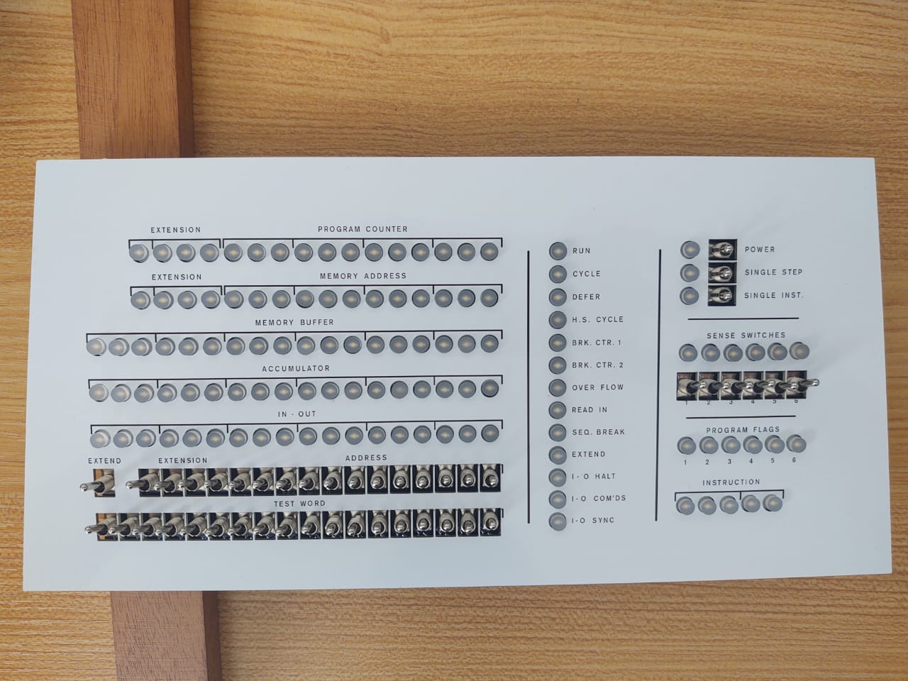
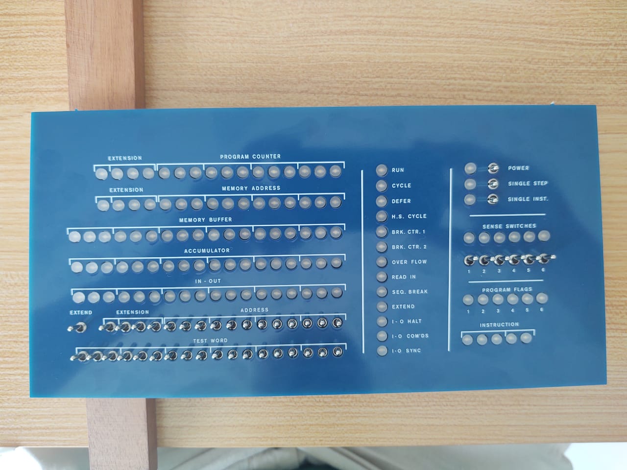
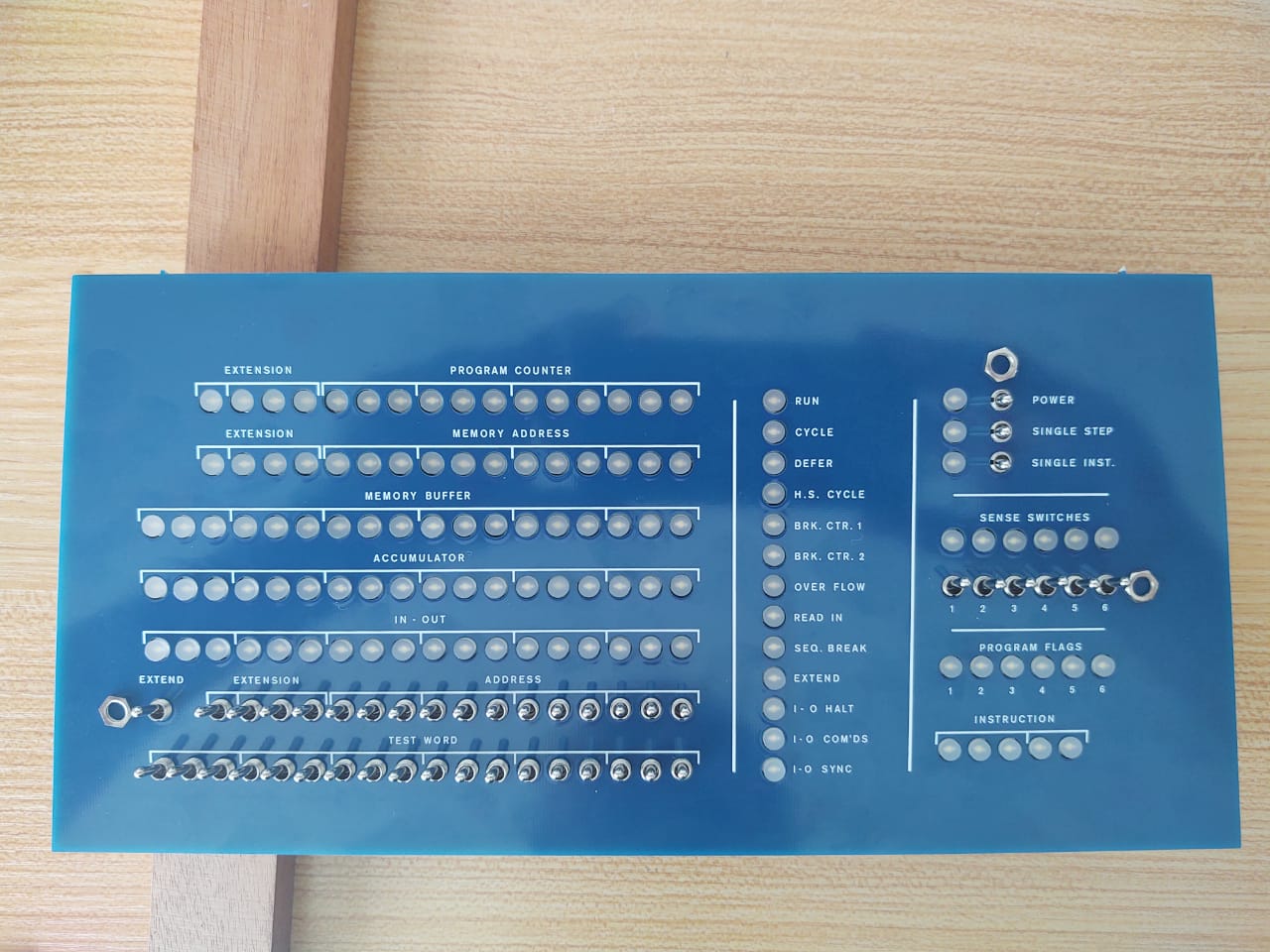
B. You can clip on blue or white front panels.
But - you'll notice that the kit contains 3 nearly identical front panel sets:
- Ottopanel: White, named after the inventor. Becomes part of the case.
- blue and white clip-on front panels. Swap them to change colours. DEC could never make up its mind, so why should you?
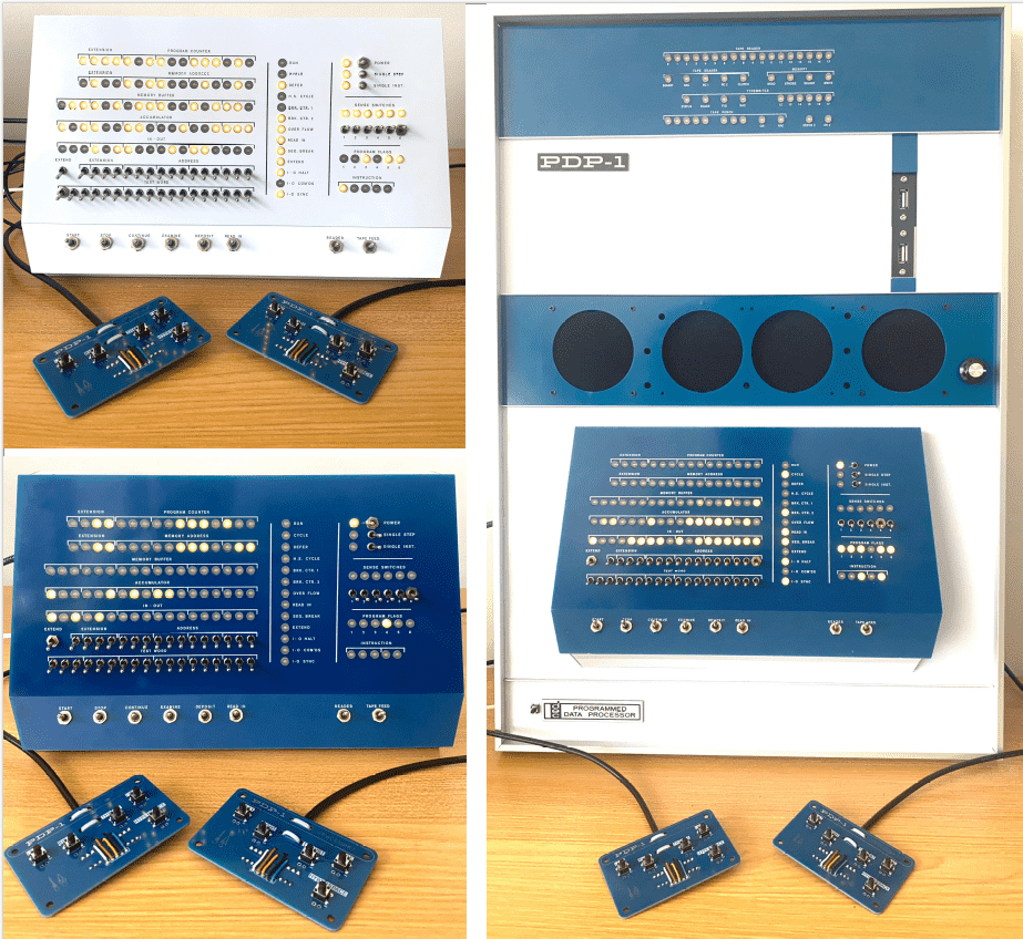
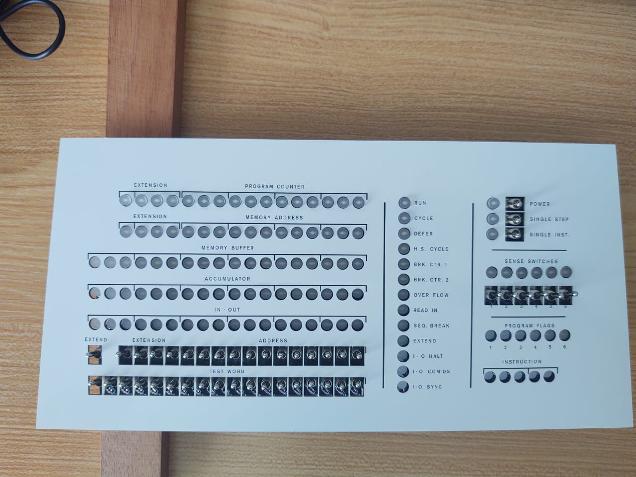
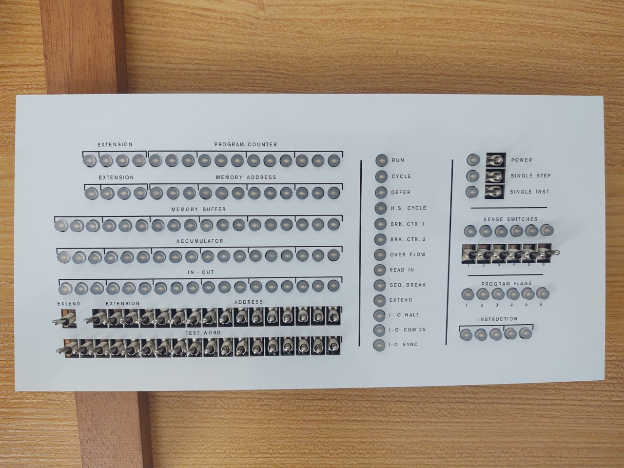
Console & Rack version, blue & white
Parts Lists
Parts List - PiDP-1 Console version
PiDP-1 Console PCB Parts:
PiDP-1 Circuit boards:
PiDP-1 Spacewar game controllers:
PiDP-1 Small Parts:
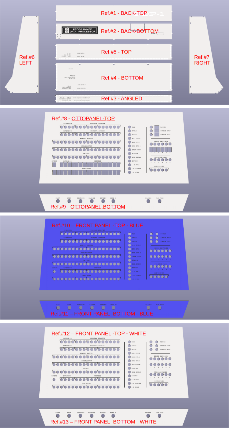
- (To the left:)
17 PCB panels in total - Switches and LEDs:
- 44 Small Toggle Switches + nuts
- 8 Large Momentary Switches + nuts
- 16 extra nuts for Momentary switches
- 119 LEDs + LED spacers
- 55 diodes, 1N4148
- 18 Resistors, 680 ohm
- 4 Resistors, 510 ohm
- ICs:
- 74HC138 IC + chip socket (U2 on PCB)
- 74HC238 IC + chip socket (U1 on PCB)
- UDN2981 or TBD62783 IC + chip socket (P1)
- Connectors:
- DE-9 Female connector
- 1*11 pin header, straight + 1*11 pin header, angled
- 11-strand rainbow connector cable, F/F
- Raspberry Pi mounting:
- 1 40-pin extra-height Pi connector
- 4 M2.5 bolts (8mm, metal) ,4 M2.5 nuts
- 4 M2.5 nylon hex spacers
- Pi 5 external power button:
- 1 tact switch, 6mm
- 2 30cm F/F Dupont ('rainbow ribbon') wires
- 2 male pin headers 1*2
- Spacewar Game Controller set:
- 2 Controller PCBs
- DE-9 Male connector, with case and nuts/bolts
- 2 meters of 5-strand cable, 5x0,14mm2, diameter 3.9mm
- 10 tact switches, 6mm
- 12 diodes, 1N4148
- 4 zip ties (2.8mm width)
Additional Parts List for the PiDP-1 Rack version
Additional parts for Rack version:
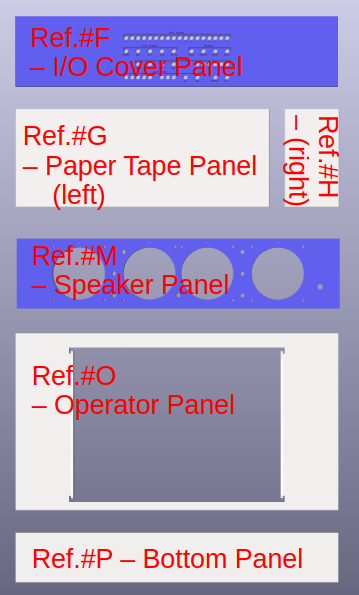
Main Rack Panels
Additional Panels
PiDP-1 Rack - Additional Parts:
- (to the left:)
18 additional PCB panels in total - Parts for IO Panel:
- 49 flat top LEDS
- 74HC04 hex inverter IC
- udn2981 or equivalent driver IC
- 1 male pin headers, 2*13 pins, straight (Mounted on main PiDP-1 PCB)
- 1 male pin headers, 2*13 pins, angled (Mounted on IO Panel PCB)
- 30cm ribbon cable 2*13 pins
- 1 4148N diode
- Parts for Speaker Panel:
- 8x M2.5 bolt/hex spacer/nut set to mount speaker back panel
- 4x M3 bolt/nut set to mount speakers in speaker panel
- Speaker foam mat
- 1x audio amplifier module
- 1x knob for audio amplifier, with mounting nut
- 3 male pin headers 1*2 for amplifier
- 1 female pin headers 1*2 (for main PCB-5V power to amp)
- 2x speaker
- 20cm red&black speaker wires to connect speakers
- 1x 3.5mm audio jack with 30cm wire to connect amplifier
- 1x USB-2.3mm audio USB dongle
2 30cm F/F Dupont ('rainbow ribbon') wires (to be cut in half!)
4 10cm F/F Dupont ('rainbow ribbon') wires (amp to speaker frame)- 2 pin headers 1*2 pins (for speaker frame)
- 2 30cm M/F Dupont ('rainbow ribbon') wires (amplifier 5V power cable)
- Parts for Paper Tape Panel:
- 2 USB Type A panel mounts with USB cable (50cm cable length)
(come with 2 mount screws each)
- 2 USB Type A panel mounts with USB cable (50cm cable length)
- Parts for Aluminum Frame:
- 2 alumimum profiles, length cm (sides of frame)
- 2 aluminum profiles, length cm (top/bottom of frame)
- 4 aluminum T profiles (spacers between panels)
- 4 metal frame corner fasteners (sets of 2 metal plates with 2 screws)
- 2 wall mount clips (sets of clip with screw)
- (4 frame spacer sets of spacer and bolt)
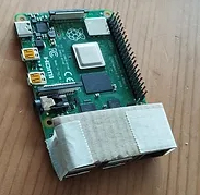
Prepare your Pi
Introduction
The pidp1 software runs fine on a 'naked' Raspberry Pi, without the PiDP-1 board. Set up your Pi before you start soldering. To play with the PDP-1 before you build the PiDP-1 hardware, we have provided an on-screen virtual front panel. So to configure your Pi for now, use pdp1control panel virtual. Enable the hardware panel again with pdp1control panel pidp before testing the hardware! The tell-tale sign: if you see a virtual front panel on your display, the PiDP-1 hardware front panel is not enabled yet. Lest you forget...
Any Pi from the Pi Zero 2 on up can be used. A Pi 4 is the minimum when you want to view the Type30 display on the Pi itself, and not through the Web interface. A Pi 5 is recommended if you also want to use the Pi as a normal Pi concurrently with the PDP-1.
The following is just FYI: you can get a terminal attached to the PiDP-1 in different ways. For now, testing using option 1 is good enough:
- 1. Use a HDMI monitor and a USB keyboard, and run everything on the Pi; for now, enable this mode through
pdp1control set gui - 2. You can also use your laptop to access the PiDP-1 over wifi, using its built-in web server: this lets you run the PiDP-1 headless.
Just place it on a bookshelf or hang it on a wall. - 3. The PiDP also has a serial port, to connect real serial terminals, or Teletypes.
It is mentioned further down in the building instructions, but for people who buy the PiDP-1 as assembled & tested: the Pi sits close to the PiDP-1 circuit board. Avoid any risk of short circuits: protect the metal USB connectors on the Pi with a strip cut from plastic or thin cardboard.
Actual Install Steps
The PiDP-1 requires the 64-bit version of the Raspberry Pi OS. First, set up your Pi like any normal Pi: create a SD card, boot the Pi with it, set up your internet connection. Then install the pidp1 software:
											cd /opt

											sudo git clone https://github.com/obsolescence/pidp1

											/opt/pidp1/install/install.sh
Answer 'y' to all questions of the install script. You can rerun the install script later to change the setup.
First look around the PDP-1
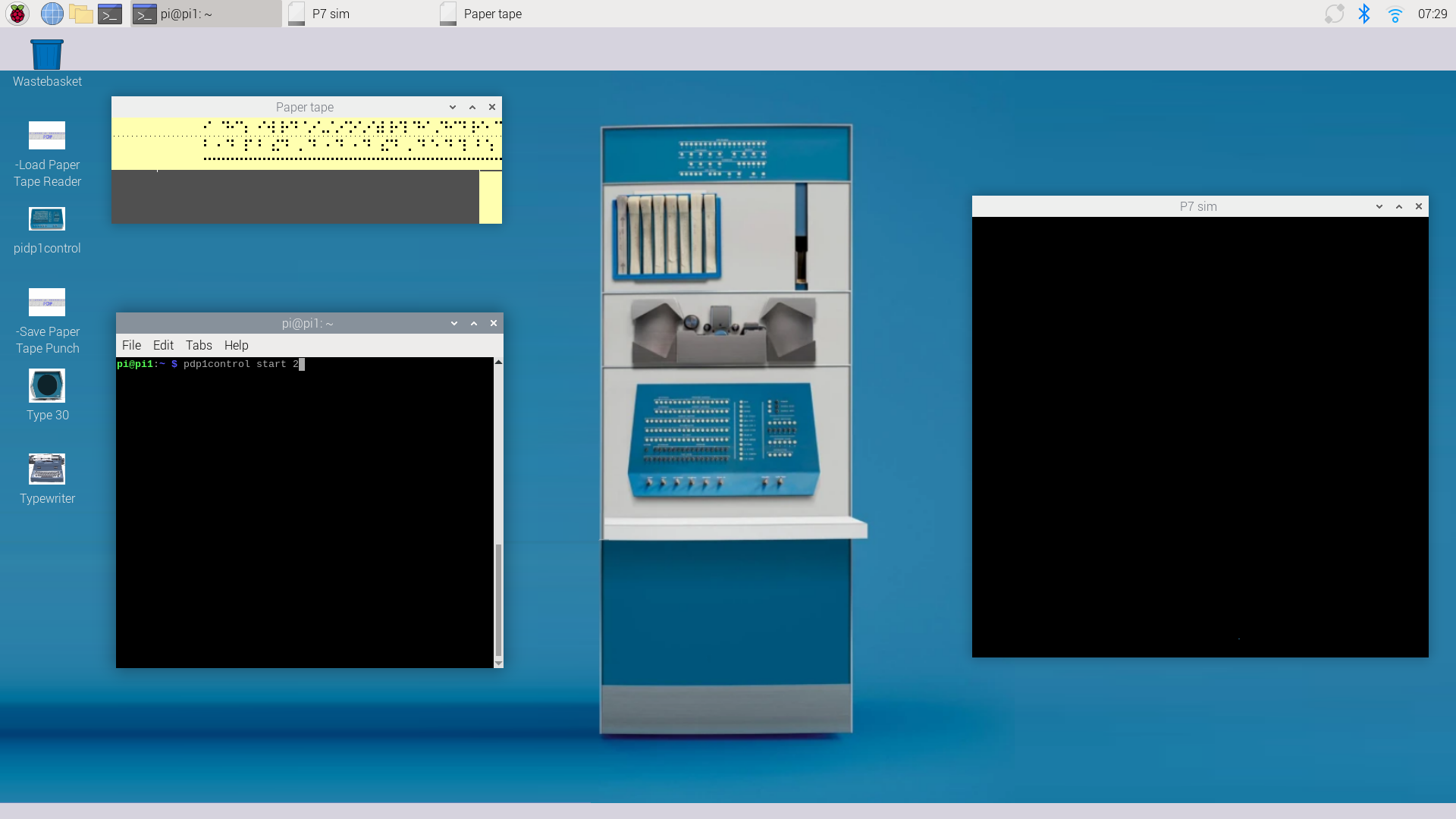
Reboot. The PDP-1 will start, but you don't have a front panel attached, so you don't see Blinkenlights. Press F11 to switch the PDP-1 display to/from full-screen. Open a terminal window. You could set things up so that you don't see any Linux. But for now, the setup is such that you can use the Raspberry Pi concurrently as a normal Pi and a PDP-1.
As you currently are still Blinkenless, use the on-screen virtual front panel. Stop the simulator with pidp1control stop, then pdp1control panel virtual and pidp1control start again. See the PiDP-1 manual for more usage information!
The manual:
It will tell you much more about how to operate the PiDP-1. It (link) is updated regularly, it is still a work in progress. Revisit now and then so as not to miss out.
Also, do not miss the subpages on gaming & demos, assembly programming, and Lisp.
The PiDP-1 Google Group:
You're very welcome to join the PiDP-1 Google Group without the actual PiDP-1 hardware by the way - our goal is to revive the PDP-1, not necessarily to sell kits.Choice of user interface:
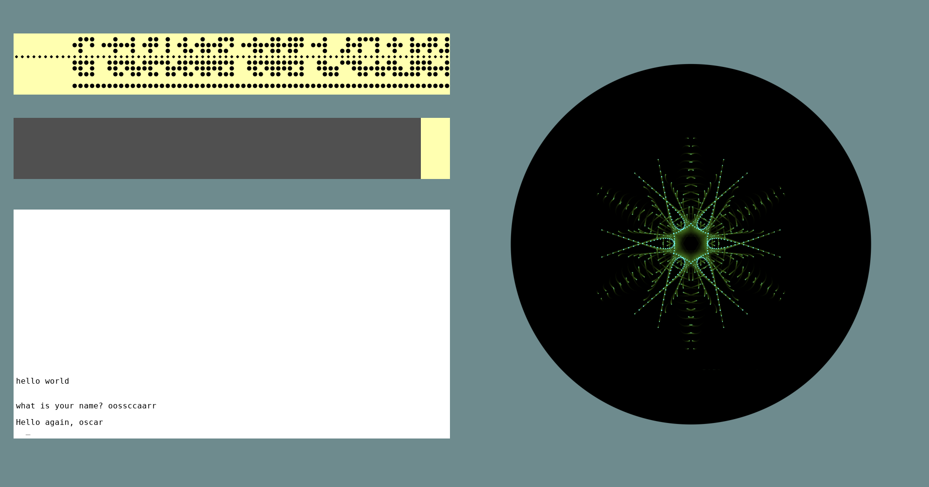
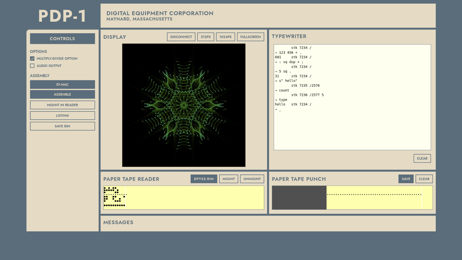
To the right: we made three different user interfaces. The GUI is meant for use on a stand-alone PiDP-1, the Web interface is ideal if you place the PiDP-1 somewhere on a bookshelf, it can remain headless and just provide everything over wifi. The Apps interface is more geared to special use cases, such as museum exhibits. It is very flexible, but requires some Linux foo.GUI interface, on the Pi: pdp1control set gui
 Web interface, remote: pdp1control set web
 Apps interface, custom setups: pdp1control set apps
 It's all a matter of preference. Start with the GUI
Time to solder. Unless you got the PiDP-1 assembled & tested of course, then you're done after inserting the Pi.
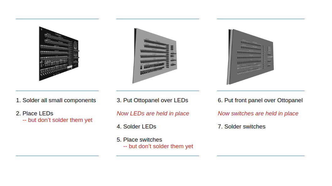
An overview of the steps to come: Small jobs: You'll build the case (✔), a narrow 8-switch PCB (✔), and the game controllers (✔).The main job is building the front panel unit (✔), which ends up as a sandwich of three panels: actual PCB, Ottopanel to help fix parts in place, then the front panel.
As follows:
1. Build the PiDP-1 case
Console Version
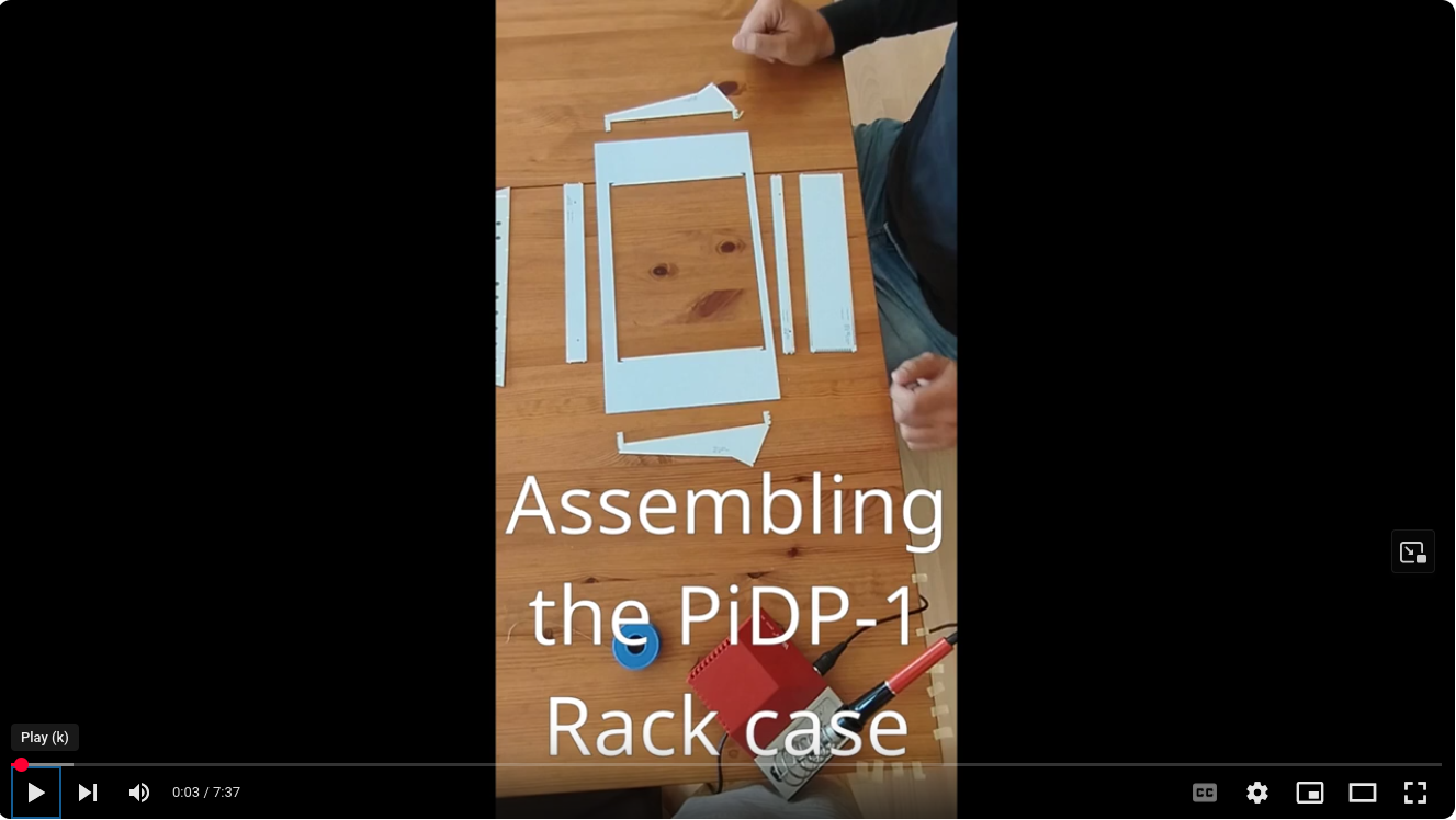
As it turned out, seeing this is much quicker than describing it in words. So please view the case assembly video below first. We apologise for not being pro Youtubers, but the content speaks for itself.
Extra tips in addition to the video
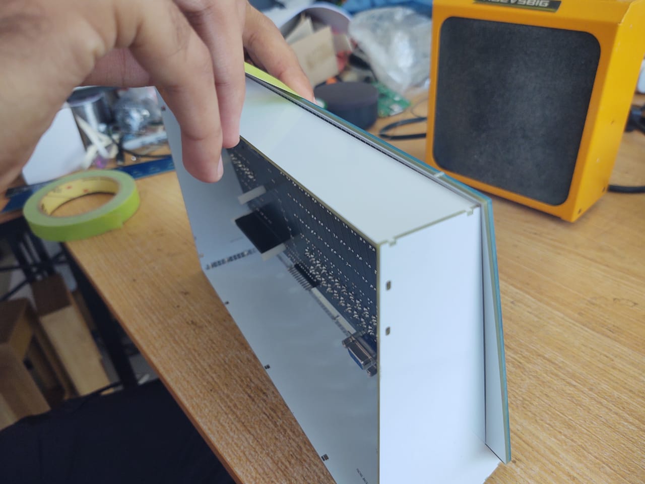
- all panels are clearly marked with text to identify them and to show which way should point to the front. Make sure this text always is on the INSIDE of the case
- check that the panels sit tightly against each other when soldering them together. If not: reheat & reseat the first solder point you made to join them
- there are guidelines on the inside of some of the panels to check you indeed solder them together straight
(although the angled front already ensures that to a large extent) - the video shows how to hold the case with one hand, soldering up with the other. It's quite easy if you follow the video
- you can't really mistake one case panel for another. With the exception of the bottom Ottopanel (Ref.#9, the part of the front panel that will hold the 8 large control switches later on). This part has Ref.#9, not Ref.#13 (check the reference numbers in the parts list above, or on the part itself). Although, if you make this mistake, not too much of a problem really.
- note that you're making most of the case here. Later on, you will add the top Ottopanel with the main PCB already attached to it. And right at the end, you can click in the top and bottom back panels.
Some pictures to add high-res clarity to the video. Click to zoom, click again to zoom further.
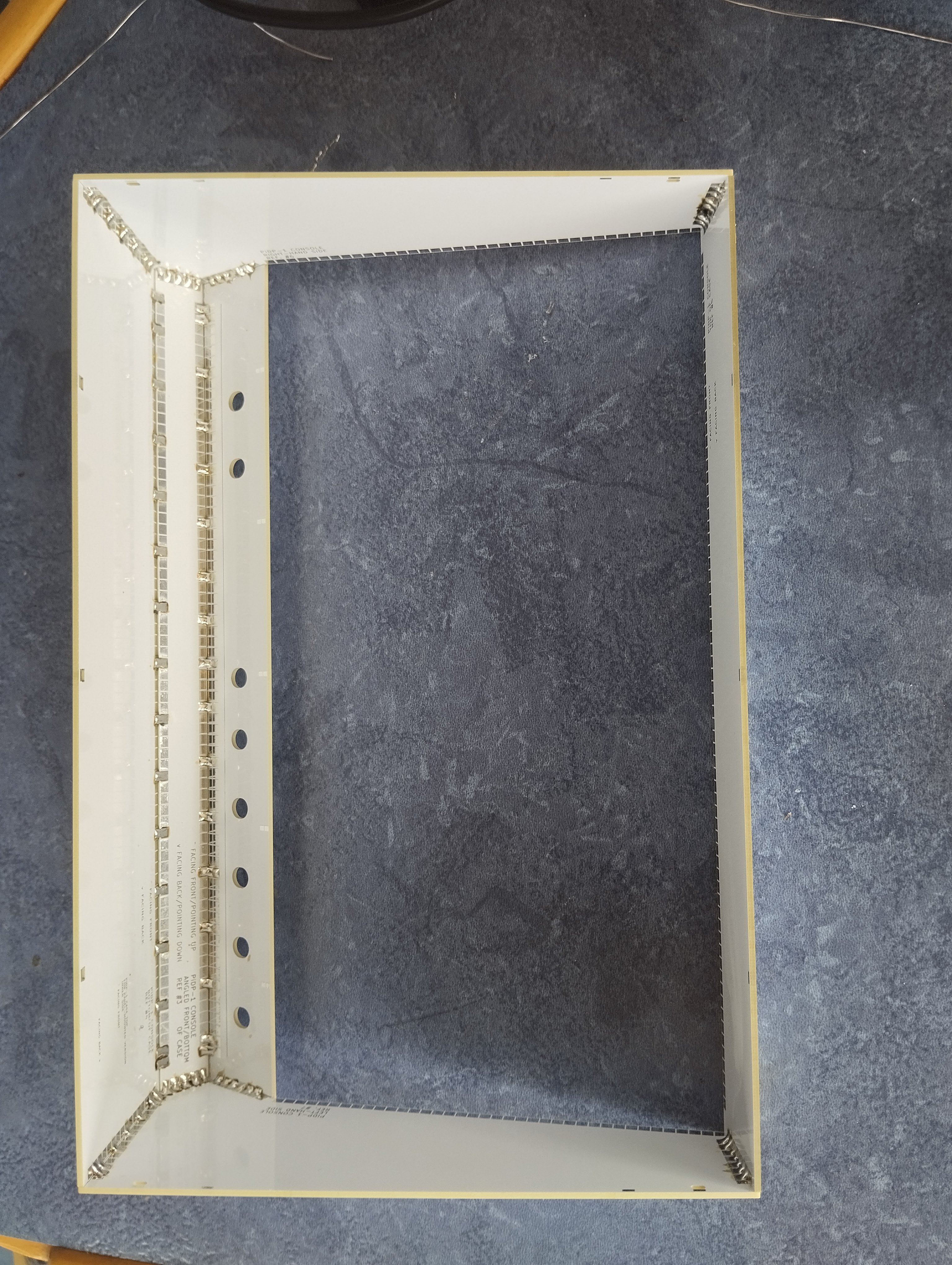
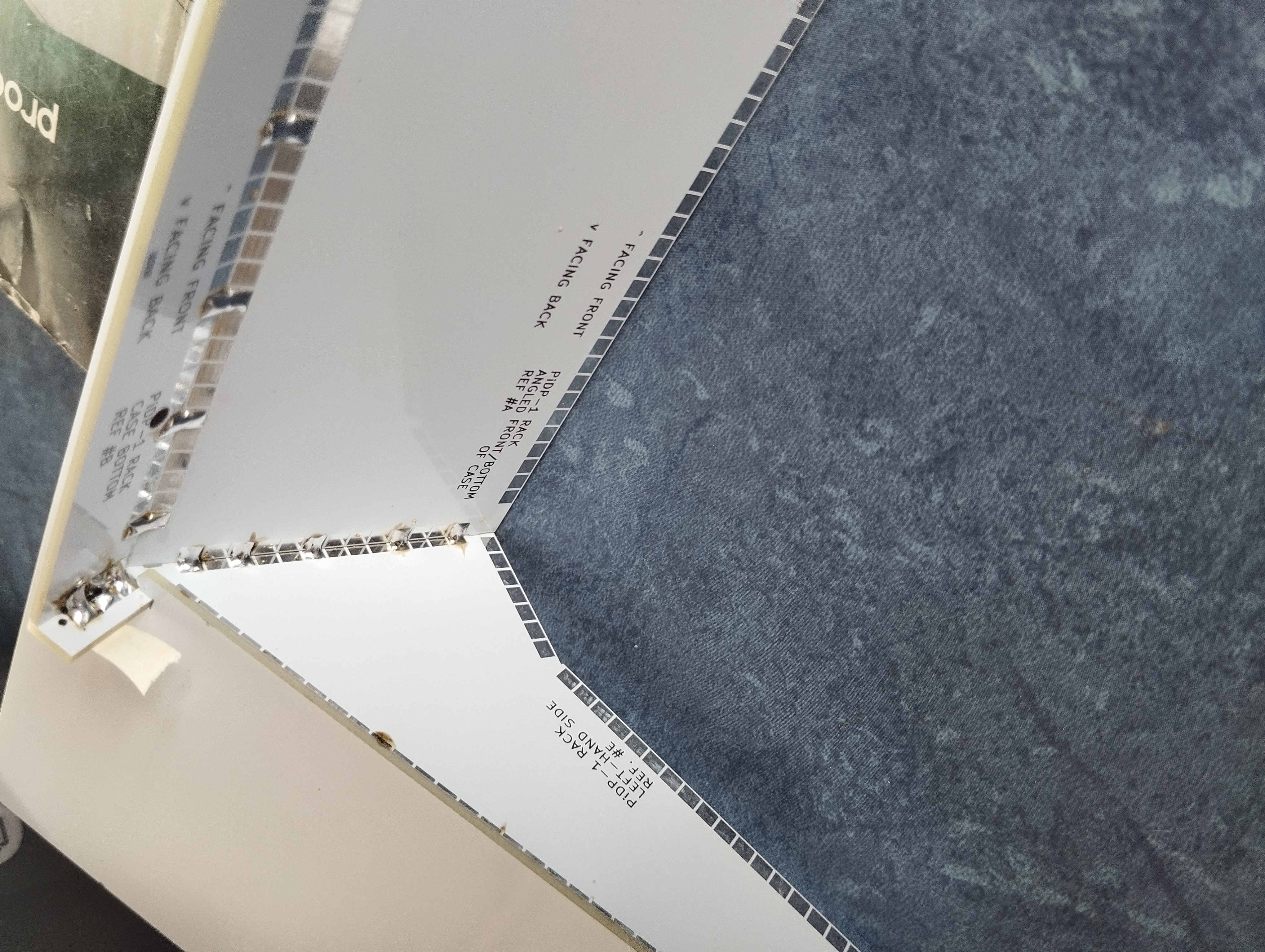
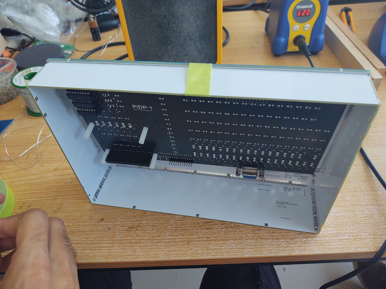
Inside view of the case once soldered up
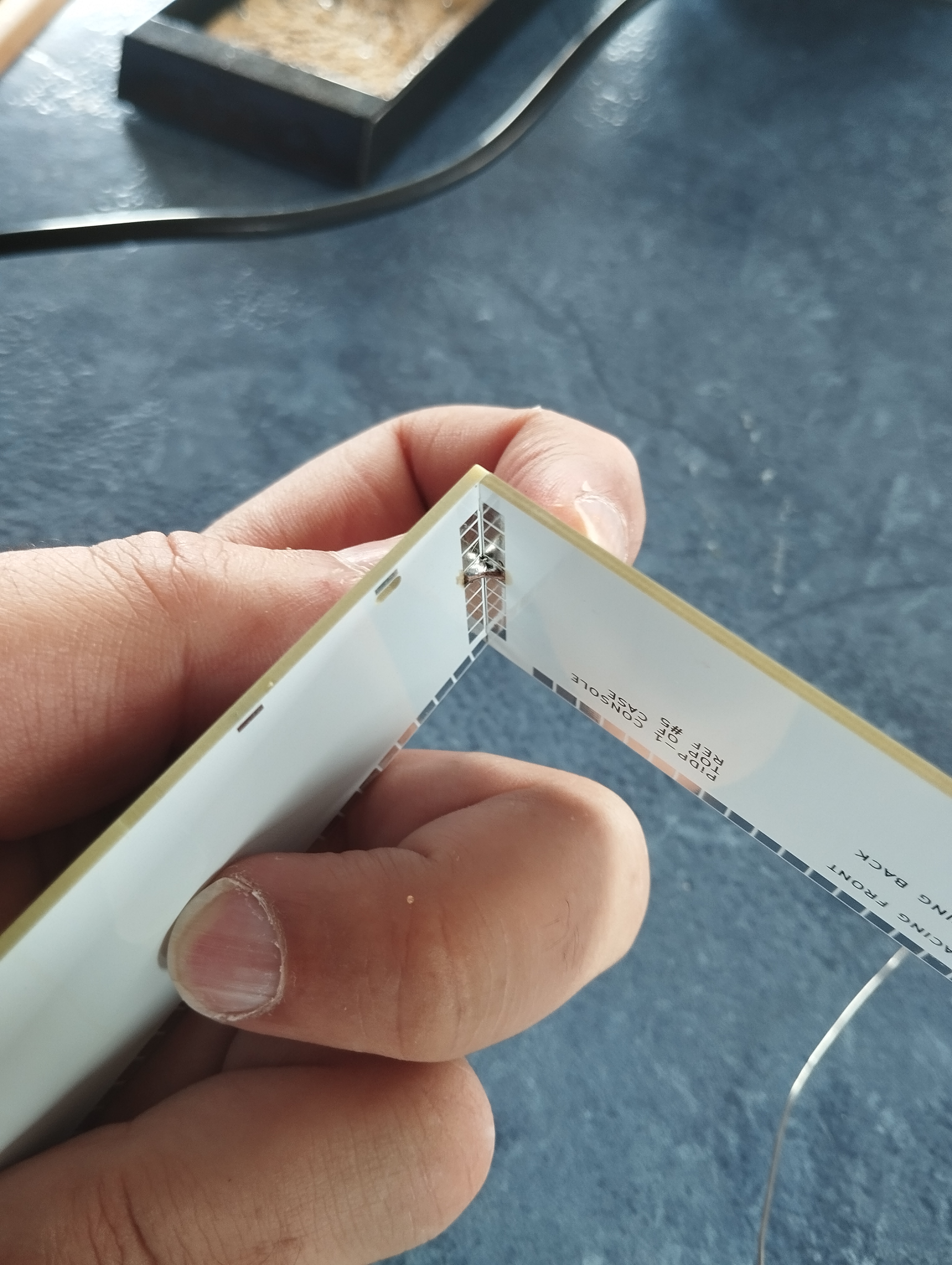
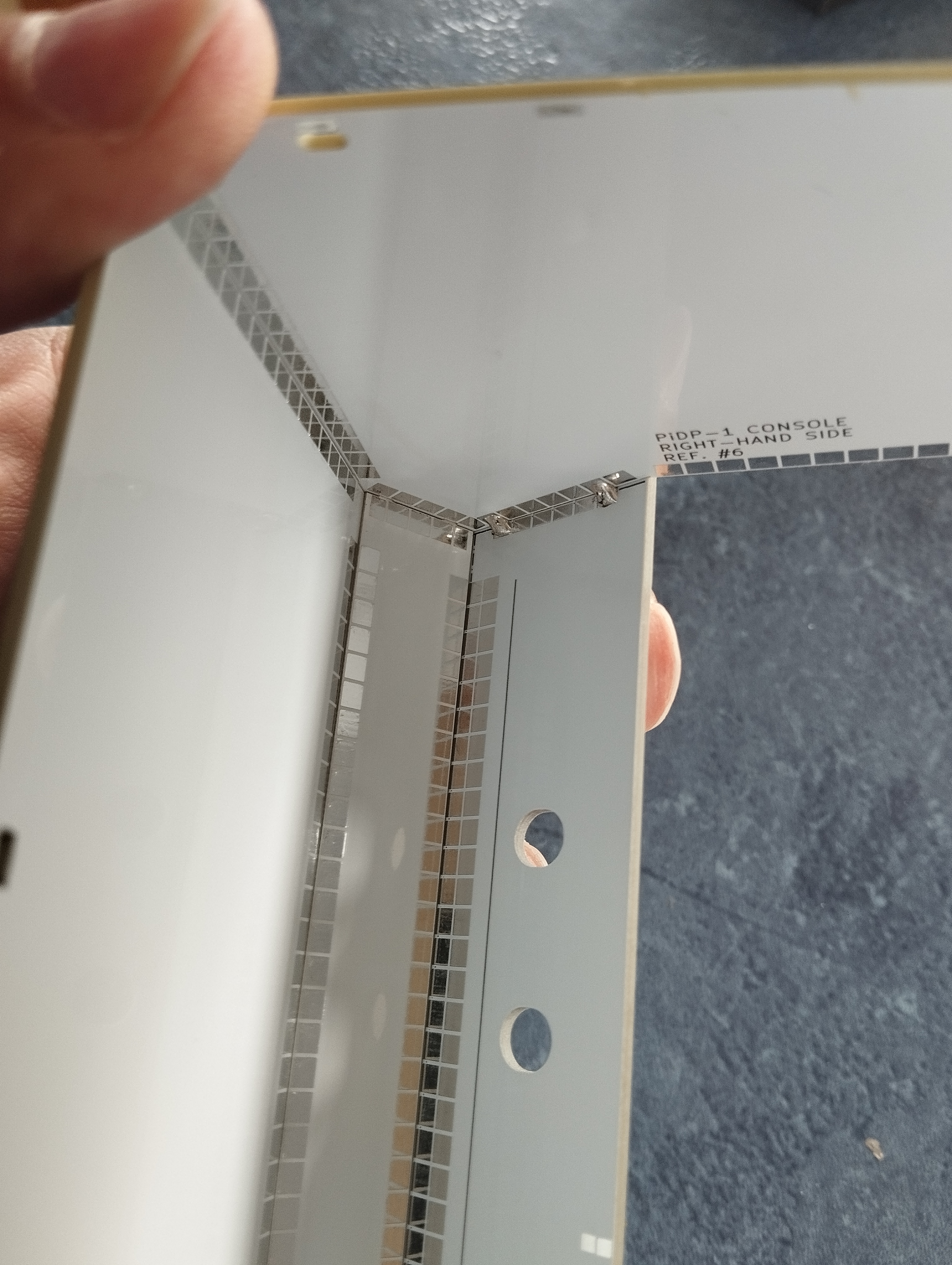
First solder joint made in top corner
First solder joints to attach bottom Ottopanel (Ref.#9)
Rack Version
Note that the Rack version also comes with the Console version's stand-alone case. We recommend that you build the Console case later, and first do the Rack case as follows:
Extra tips in addition to the video
- all panels are clearly marked with text, identifying them and which way should point to the front. Make sure ALL panels have this text on the INSIDE of the case
- check that the panels sit tightly against each other when soldering them together. If not: reheat & reseat the first solder point you made to join them
- there are handy guidelines on the inside on the panels to check you indeed solder them together at straight 90 degree angles
(although the angled front already ensures that to a large extent) - the video shows how to hold the case with one hand, soldering up with the other. It works well, but having the help of a friend makes it (even) easier
- you can't really mistake one case panel for another. With the exception of the bottom Ottopanel (the part of the front panel that will hold the 8 large control switches later on). This part has Ref.#9, not Ref.#13 (check the reference numbers in the parts list above, or on the part itself). Although, if you make this mistake, not too much of a problem really.
- note that you're making most of the case here. Later on, you will add the top Ottopanel with the main PCB already attached to it. And right at the end, you can click in the top and bottom back panels.
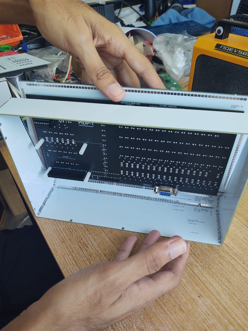
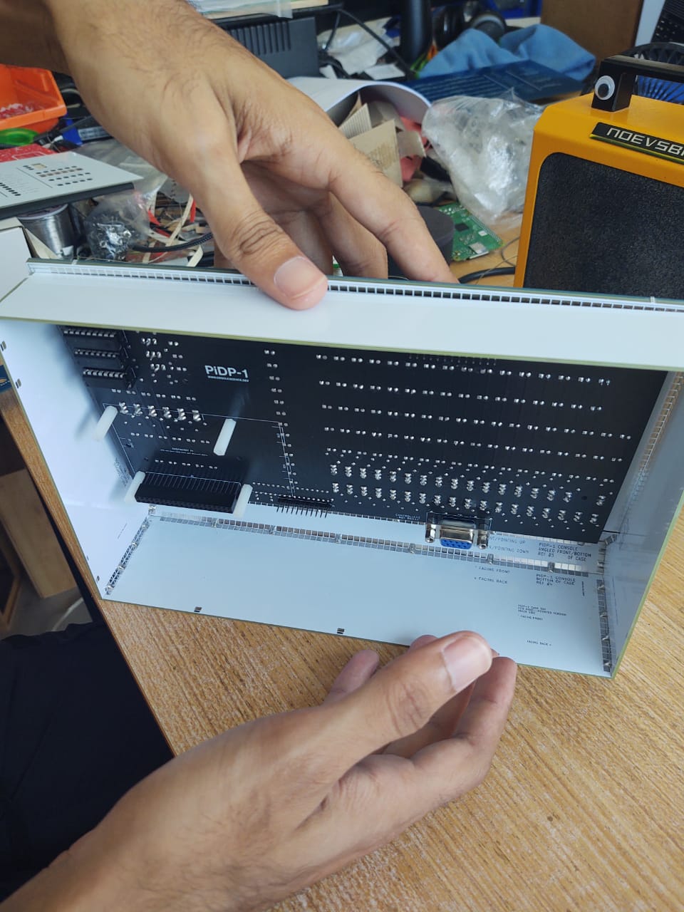
Some pictures to add high-res clarity to the video. Click to zoom, click again to zoom further.
Inside view, fully soldered up
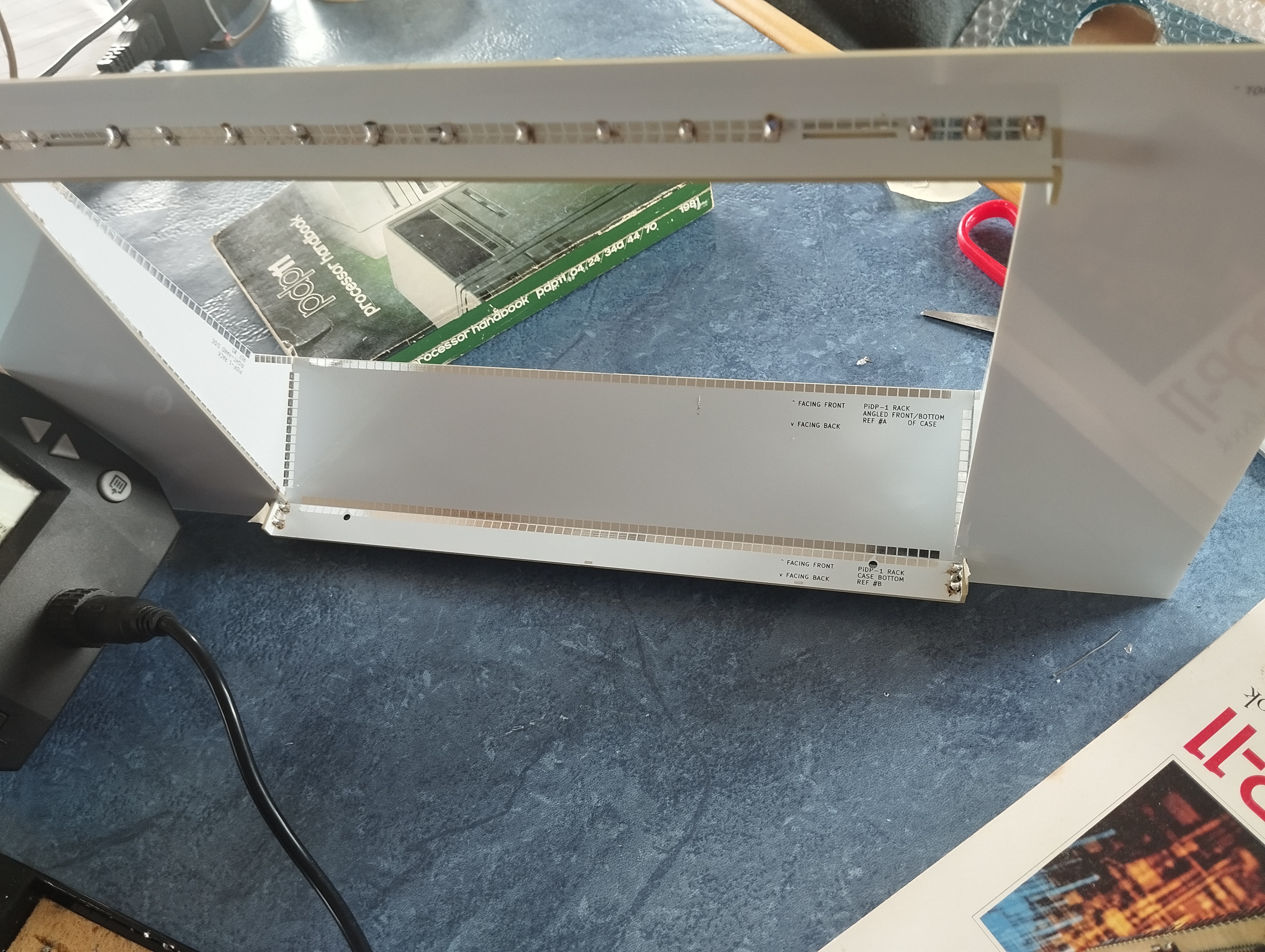
View from the back, after soldering up the top panel
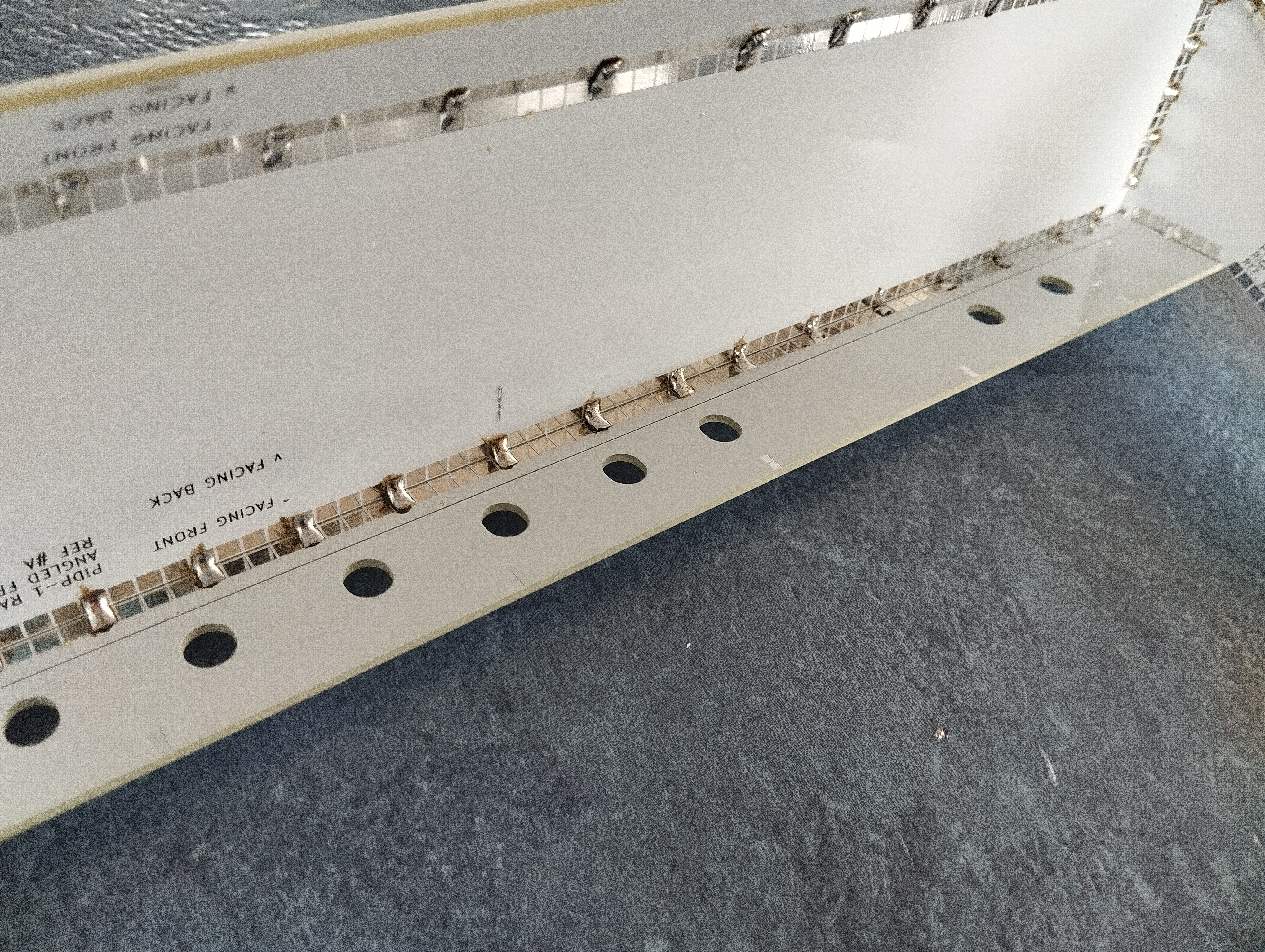
Fully soldered up with joints every 5 tabs
2. Soldering the main PCB set
Introduction
If you’ve never soldered before: keep the tips below in mind. The PiDP-1 is a good first soldering project, as there’s lots of simple 2-pin parts to practice on. And the few other parts are simple through-hole parts as well. Just keep in mind:
Good solder flows, bad solder clings to your iron. I like Stannol HS10, but google for other good brands (leaded, always leaded and not unleaded). Set your soldering iron to the lowest comfortable temperature, which should be around 275-325 degrees C - just set it as low as is comfortable. Do not overheat parts, especially switches, by touching them with the soldering iron for too long! A few seconds max.
You’ll want a side cutter to clip off the long leads from LEDs etc, after soldering them on.
Tip: use masking tape (not really sticky tape) to fix components flush to the PCB when soldering them in from the other side.
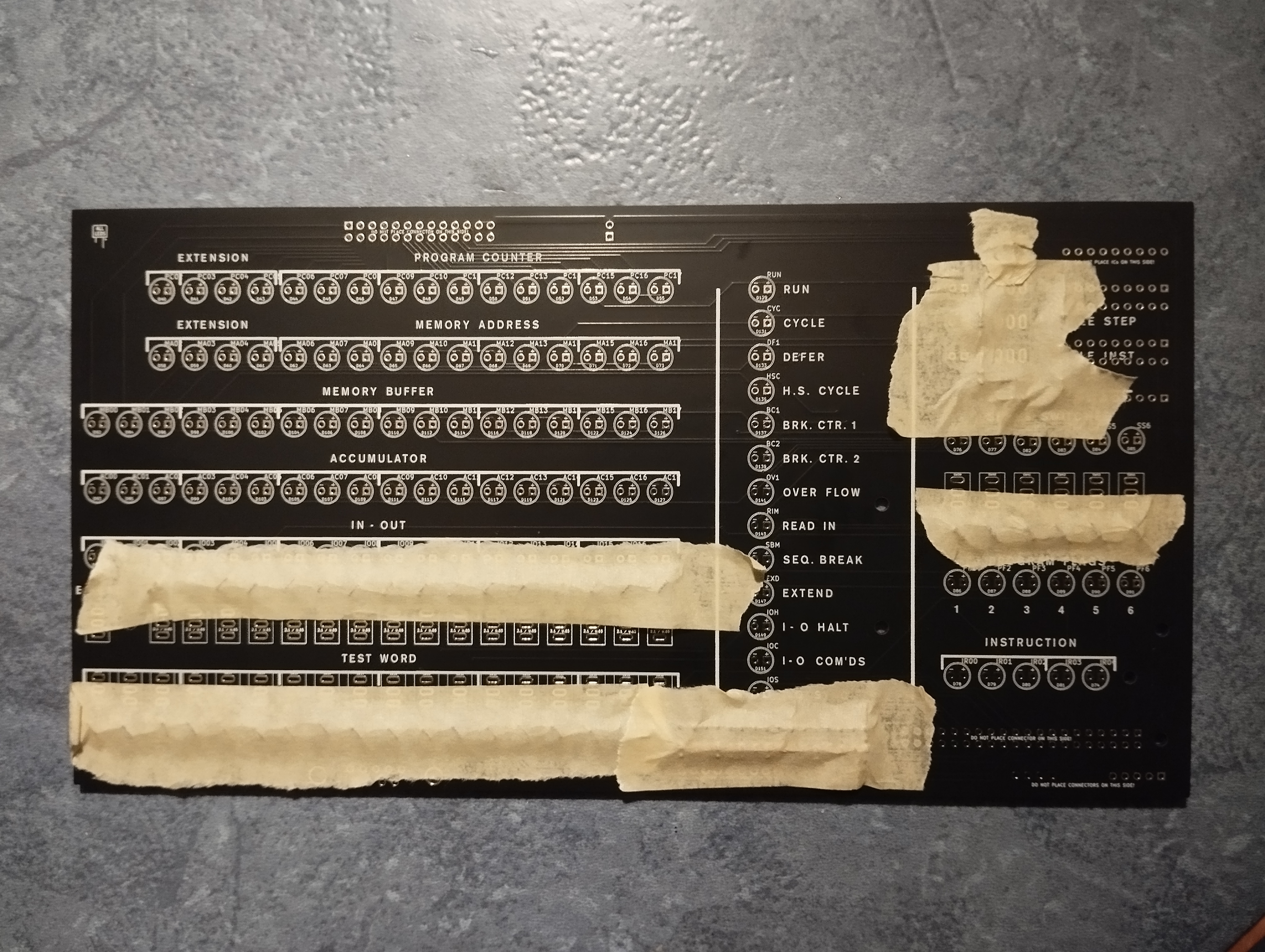
Time saver: all diodes & resistors taped up on the front side, ready to solder everything in one go on the back.

Time Saver II: A good side cutter. They're only a few dollars.
Top PCB - Soldering the small parts
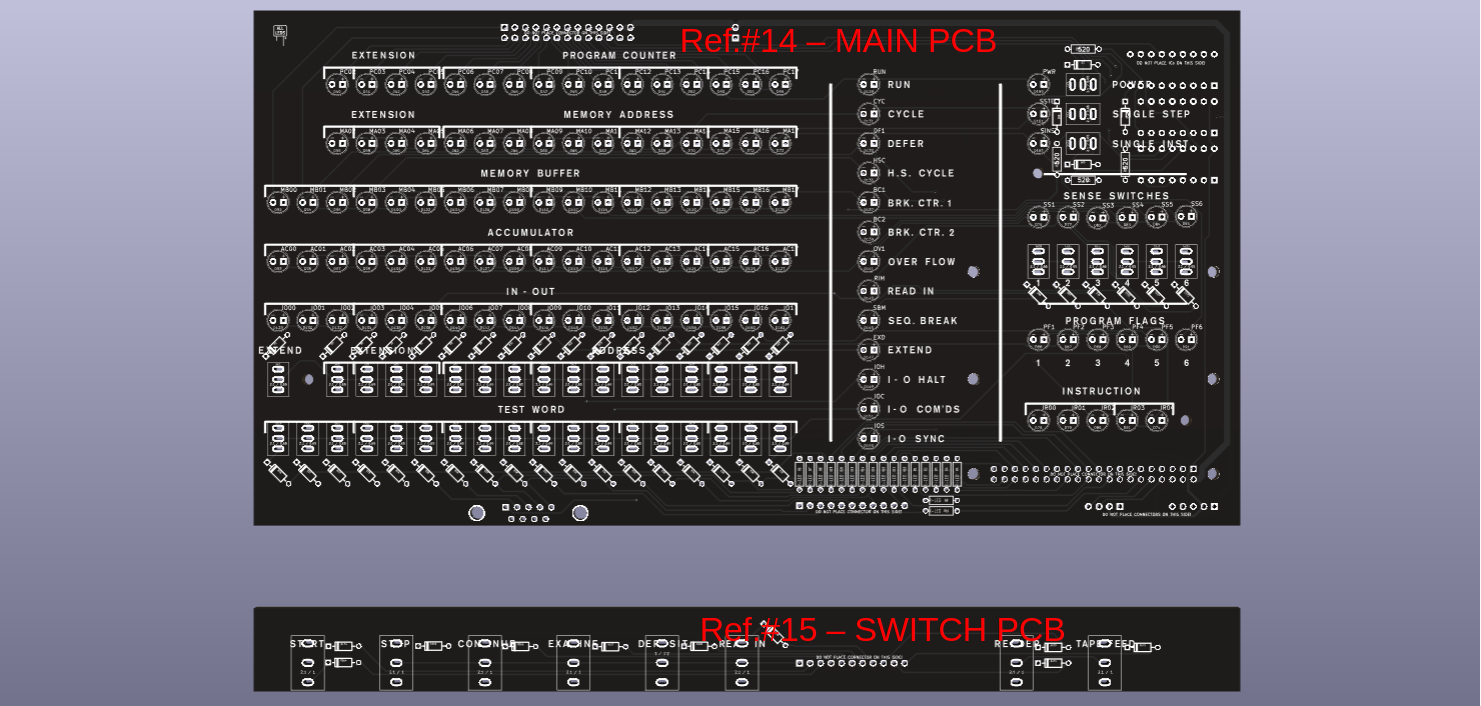
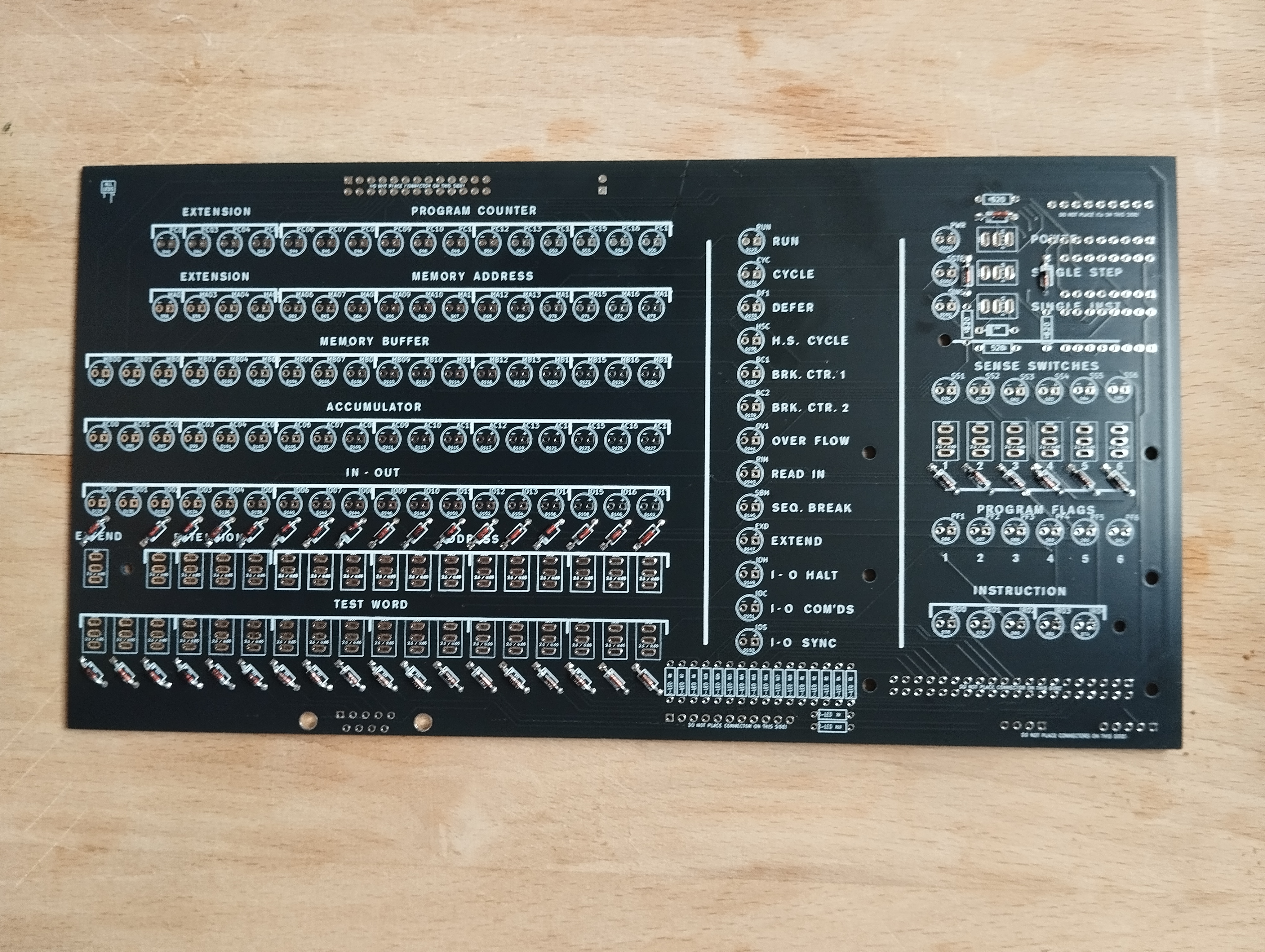
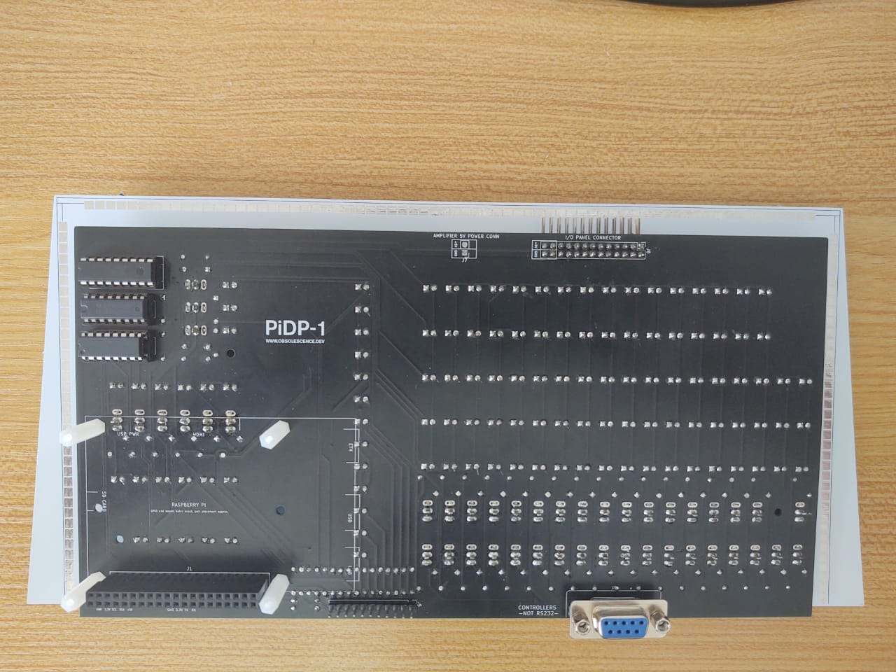
Parts are mounted on the front and back side of the PCB (PCB Ref.#14), be VERY careful not to solder parts on the wrong side.Front side of the Lights Panel:
 1. Solder the diodes, there is one for every switch plus one more at the top right. Polarity matters! Match the black stripe on the diode with the white stripe on the diode's footprint on the PCB
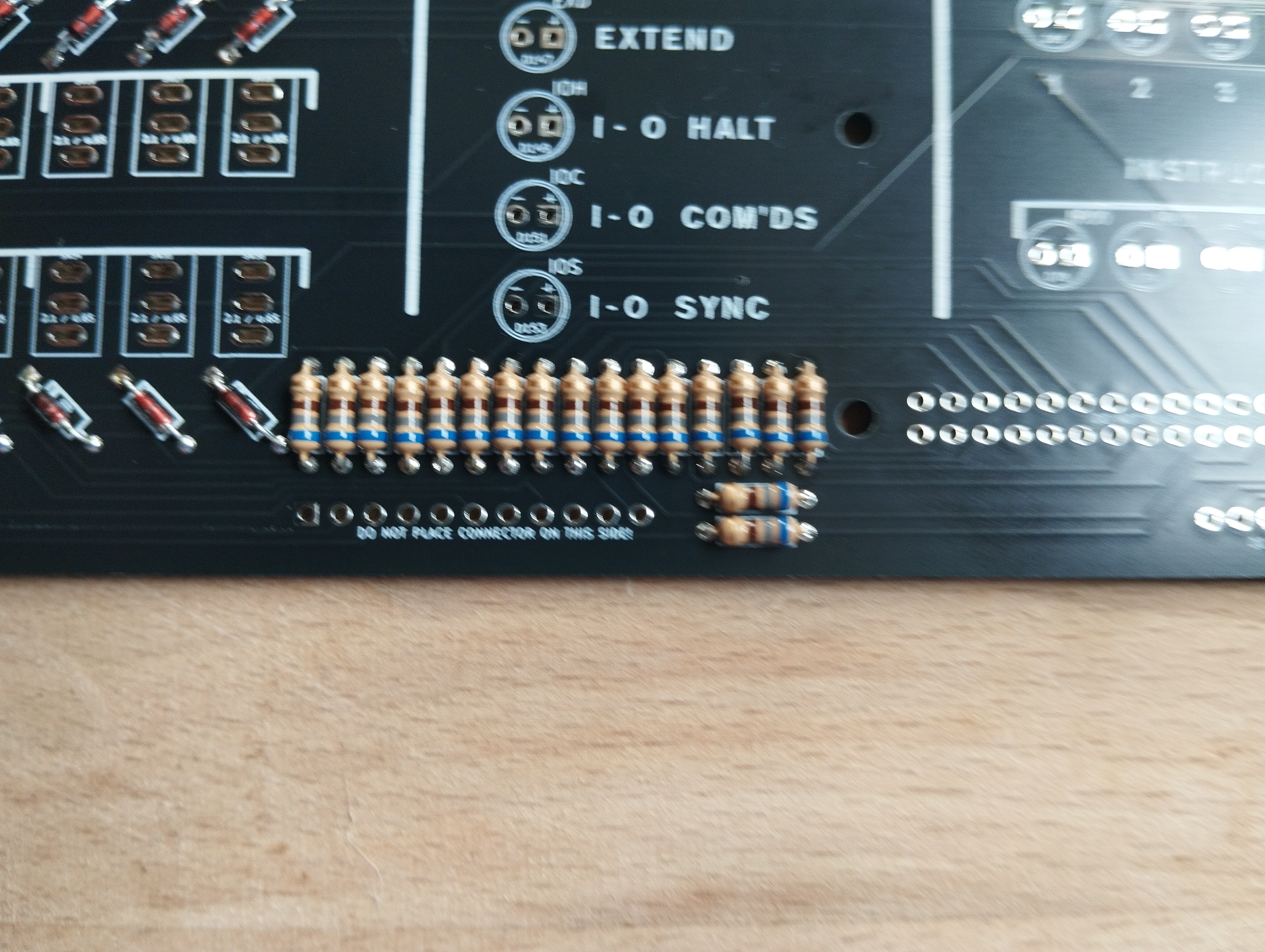 2. Add 18 resistors, 680 ohms, on the footprints marked as R_LED, near the GPIO connector at the bottom.
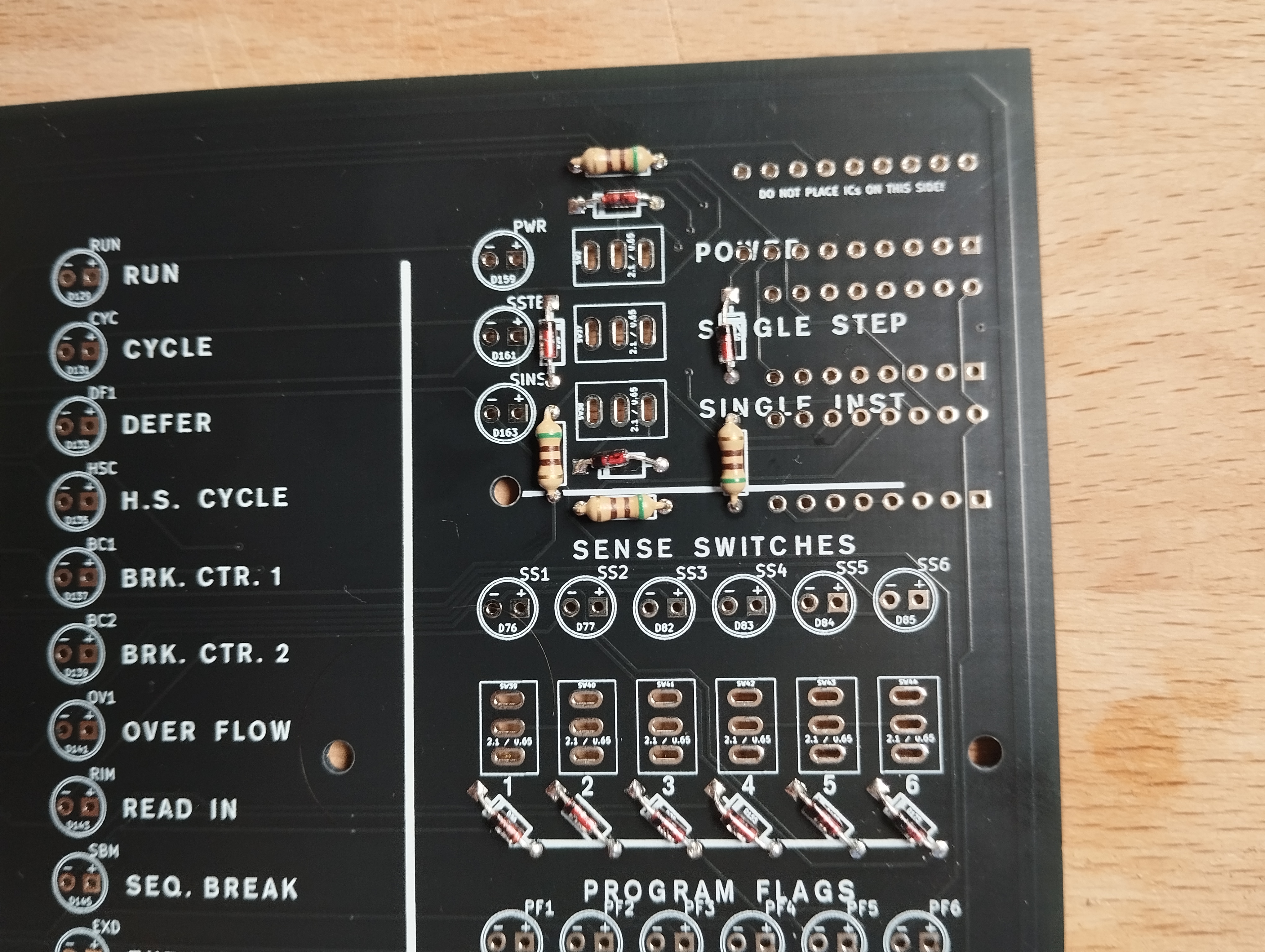 3. Add 4 more resistors, 520 ohms, around the three chips at the top right of the board. (note the diode here, too)
Back side of the Lights Panel:
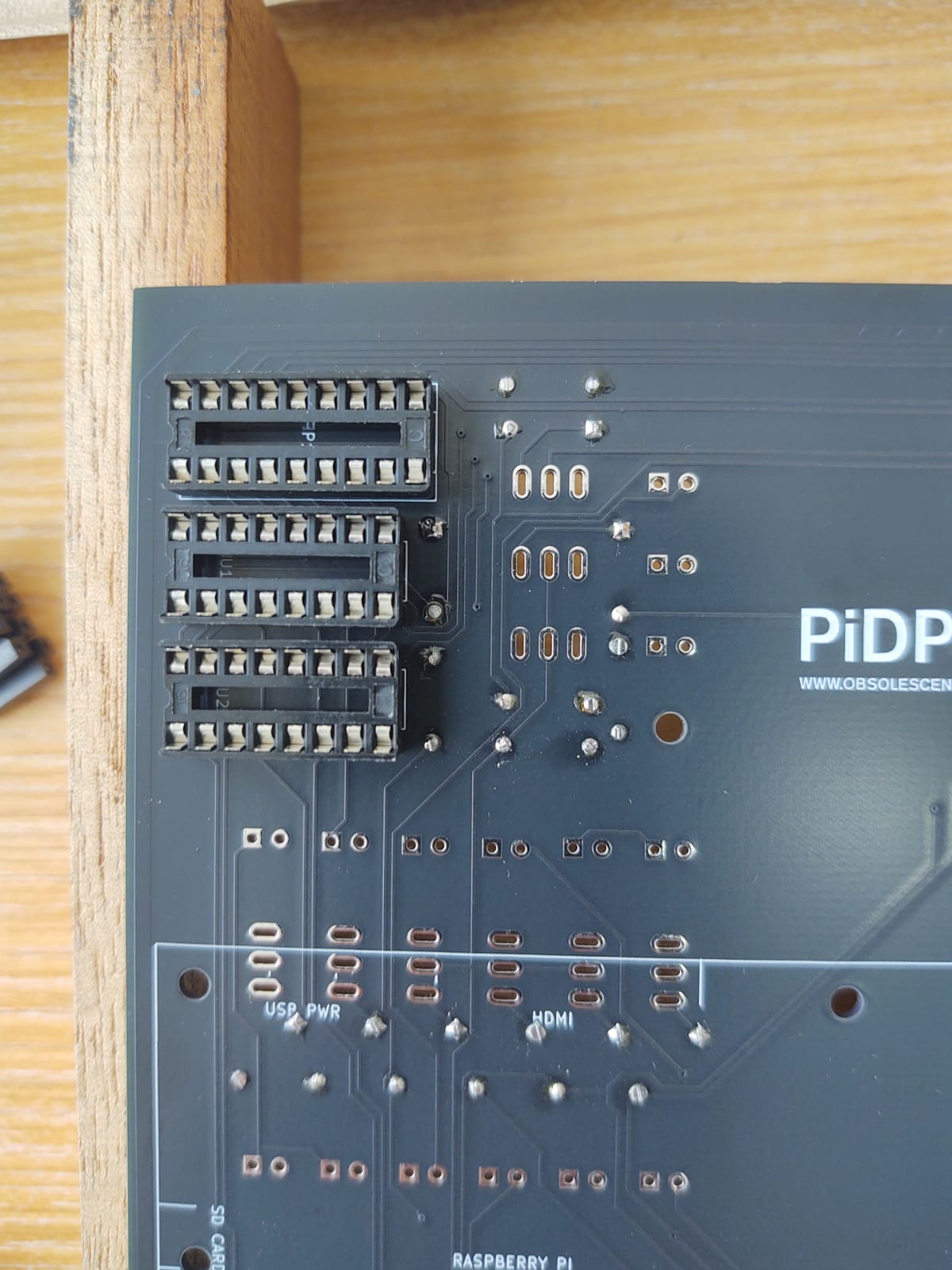 4. Three chip sockets for the 3 ICs, on the BACK side. Match the notch on one side of the socket to the notch on the PCB footprint
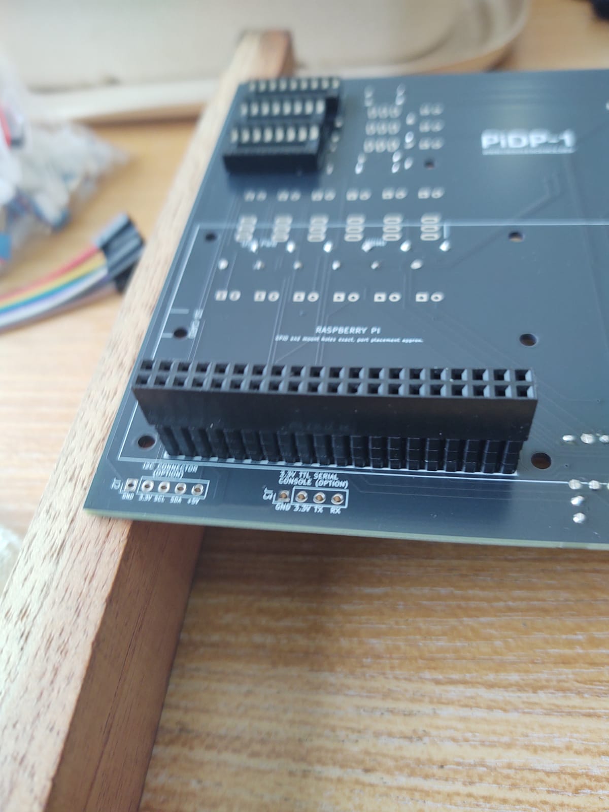 5. Solder the GPIO connector. On the BACK side of the PCB.
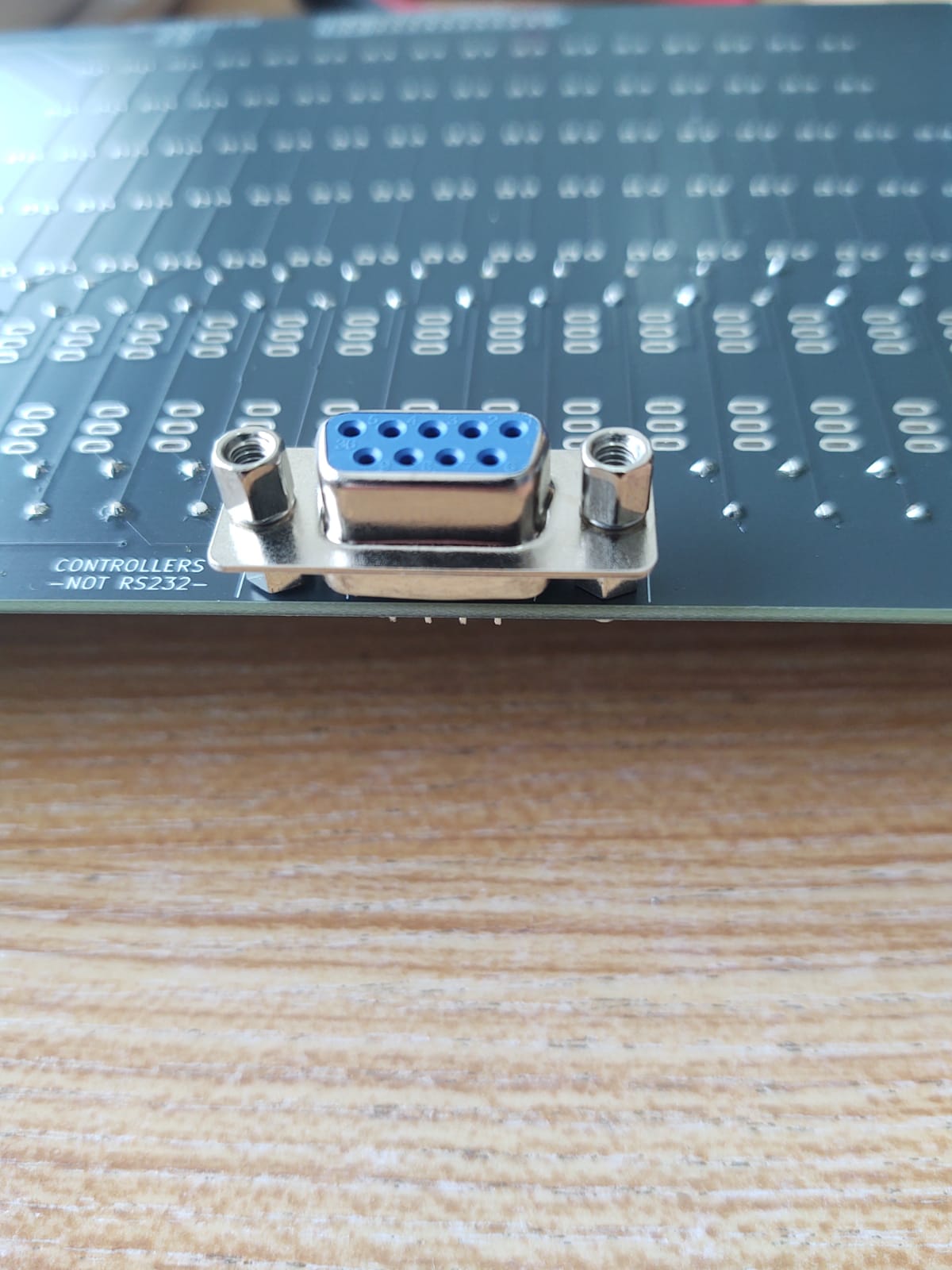 6. Solder the the DE-9 connector on the back side
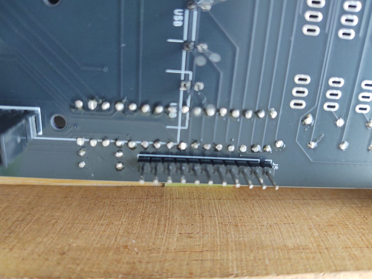 7. Solder the 1*11 pin header (the straight, not the angled one) on the back side
 8. For Raspberry Pi Zero mounting: 4 nylon M2.5 spacers fixed with 4 black M2.5 nuts.
8. For Raspberry Pi 5/ Pi 4 mounting: 4 nylon M2.5 spacers fixed with 4 black M2.5 nuts.
8. For Raspberry Pi Zero mounting: 4 nylon M2.5 spacers fixed with 4 black M2.5 nuts.
8. For Raspberry Pi 5/ Pi 4 mounting: 4 nylon M2.5 spacers fixed with 4 black M2.5 nuts.
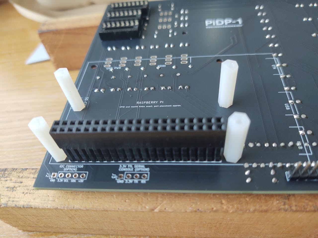
Details on step 8: the spacers that will hold the Raspberry Pi
- Put 4 nylon M2.5 spacers in from the back of the PCB. From the PCB front, fix them in place with 4 black M2.5 nuts. Keep the 4 M2.5 bolts (to screw on the Pi) apart for when you are mounting the Pi later on.
- Two of the nylon spacers go next to the GPIO connector. But note that there are two more mount holes fitting the smaller Pi Zero 2W and two other mount holes for the larger Pi 4/5. So there are mount holes for both types of Pi. Choose the right ones for your Pi.
- Note that the Pi 4 nylon spacers in the photo are positioned to hold a Pi Zero, not a Pi 5
Only if you are building the Rack version of the kit, there is a step 9
- Add the 2*13 straight pin header (not the angled one) at the top of the PCB. It will connect the I/O panel.
- Add the 1*2 FEMALE pin header, also at the top. It will provide power to the speaker panel's amplifier.
Add solder tabs to the top Ottopanel
Before you add the LEDs and switches in the next section, there is one more thing. But it makes sense to first explain what this about.
Explaining the solder tabs
In pictures, click to zoom:
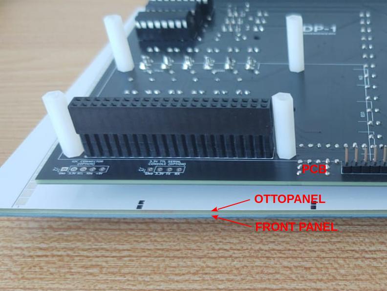
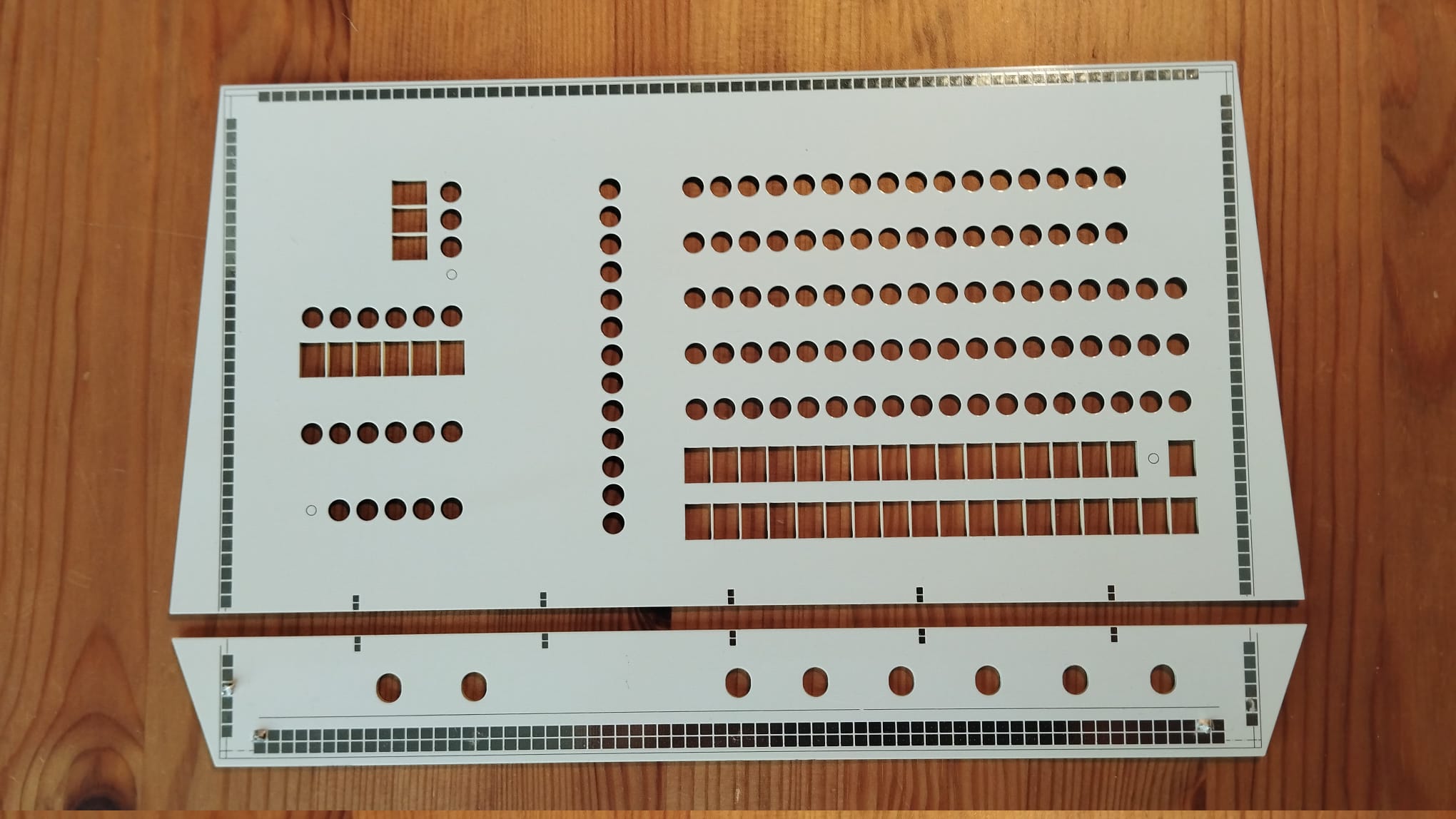 Here you see the two Ottopanels, top and bottom, that will hold the actual front panels. Note the small, vertical solder pads along their shared edge. Soldering small pins across the boards will join the two panels firmly. That is the idea.
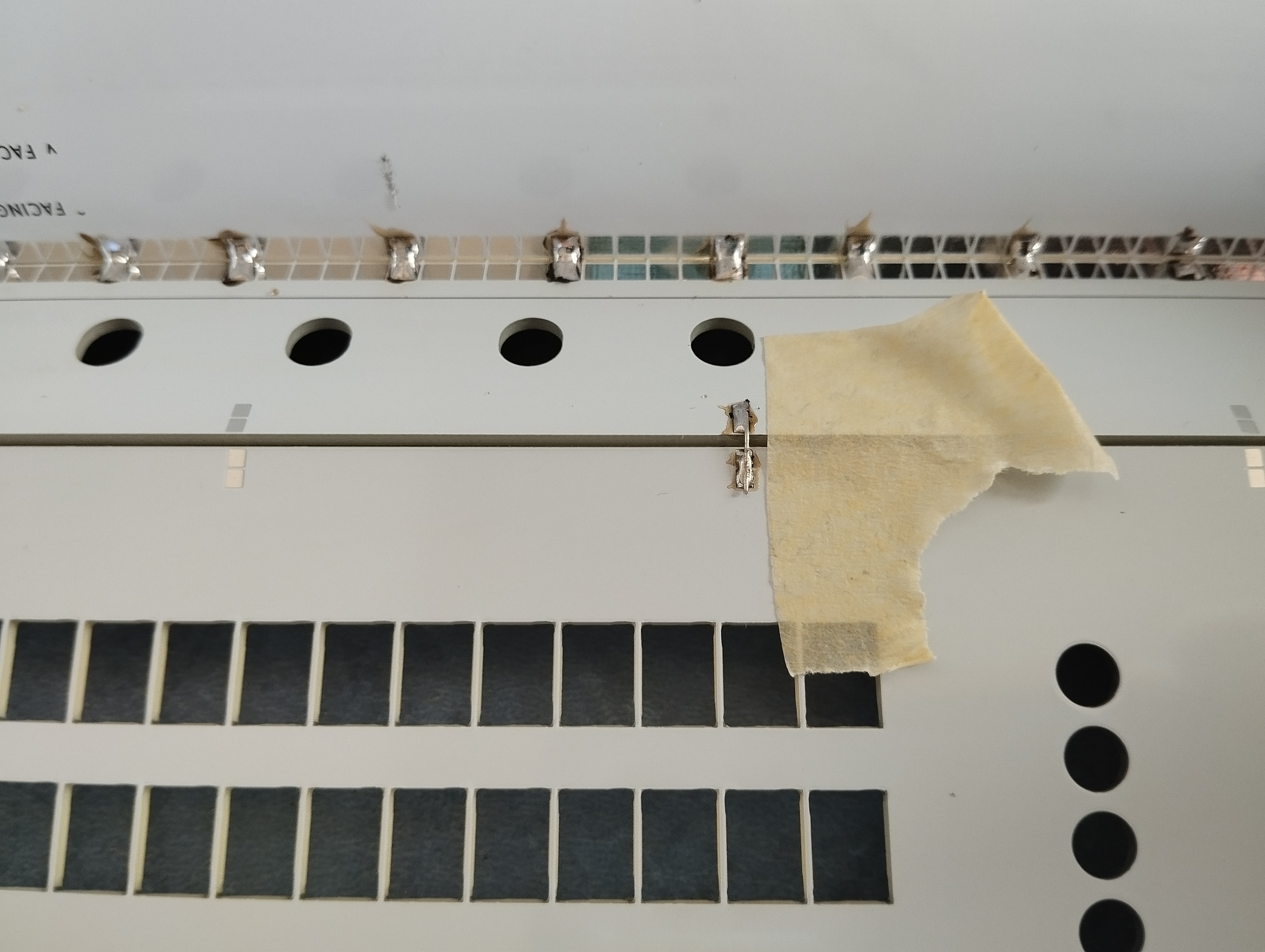 Here is a close-up showing one of the solder tabs, next to the ugly bit of masking tape.
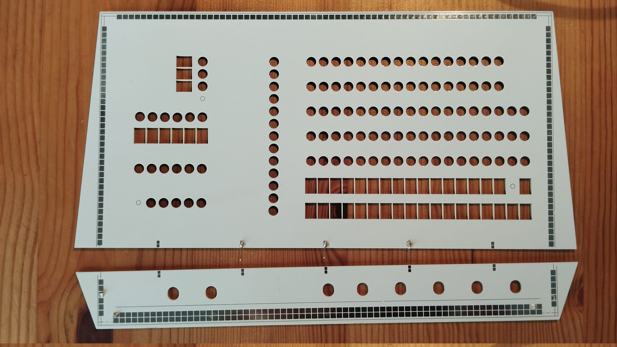 Overview - 3 tabs soldered (there's 5, but it's overkill)
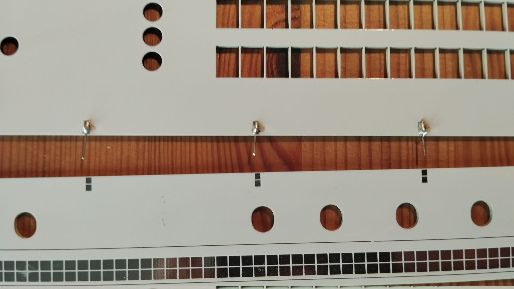 Close-up - 3 tabs soldered
Top PCB - adding the lights & switches
Make sure that you have all the previous parts on the board before proceeding. Because if you have to redo any of the steps above, the next step of removing and fitting the Ottopanel again is a bit fidgety (though not a problem really). All the parts are on? All their pins are soldered? Check.
Soldering the LEDs:
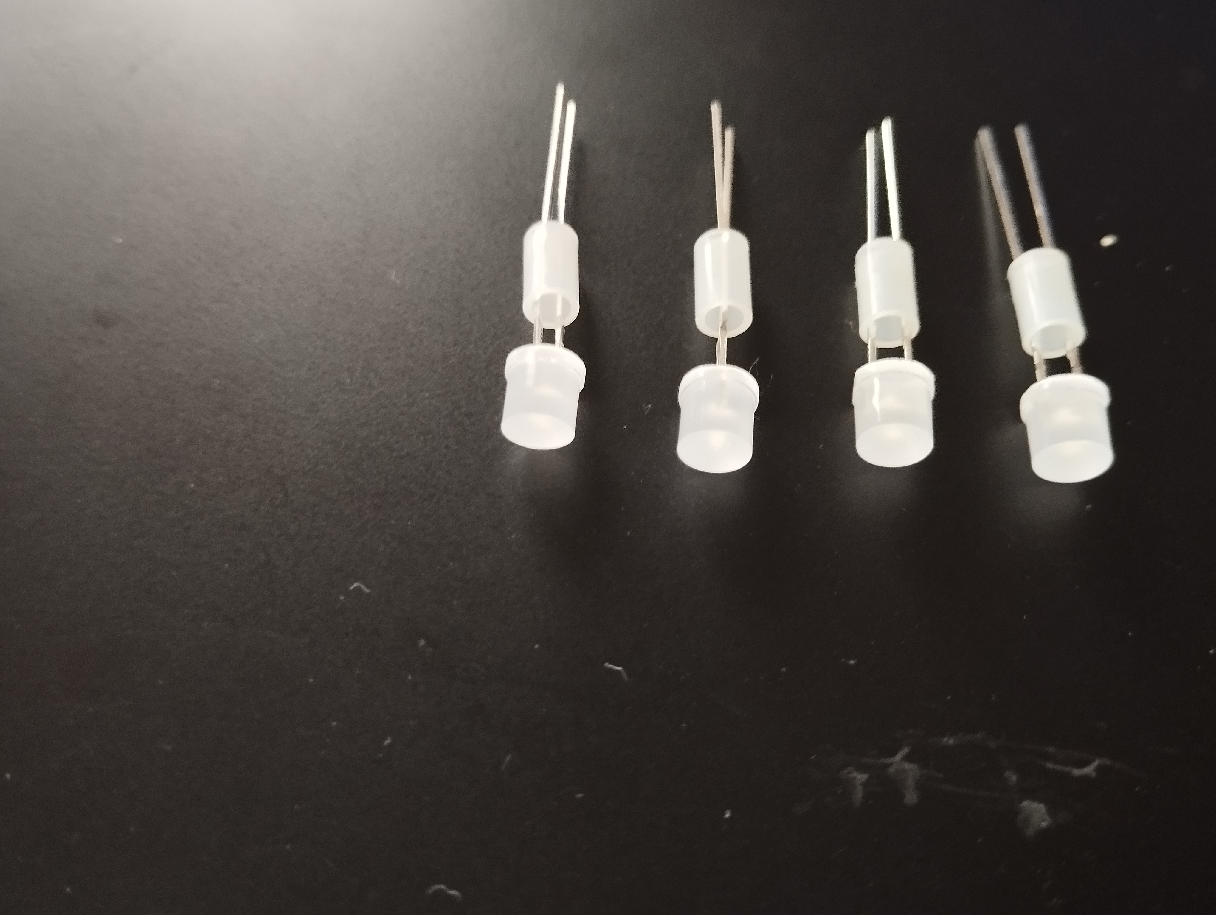
There are 119 LEDs but actually, soldering them in goes rather quickly, thanks to the Ottopanel (Ref.#8). Alas, it does start with a little chore: put a LED spacer on each LED.
LED spacers are actually a great help when putting in LEDs. When you know how to use them; see the pictures below. The solid end of the spacer goes onto the PCB, the hollow end faces the LED. Put the LED into the spacer, with its pins only protruding a bit. Now mount the LED+spacer onto the PCB. Once the LED is in, press it in all the way. A faint click, and the LED is solidly in the right place. But best press the LED in with two fingers, not one.
 Fit LED spacers to all LEDs
Polarity matters!
See the little marker on the PCB's top left, it shows they should be put in. Long pin to the right (seen from the front of the PCB).
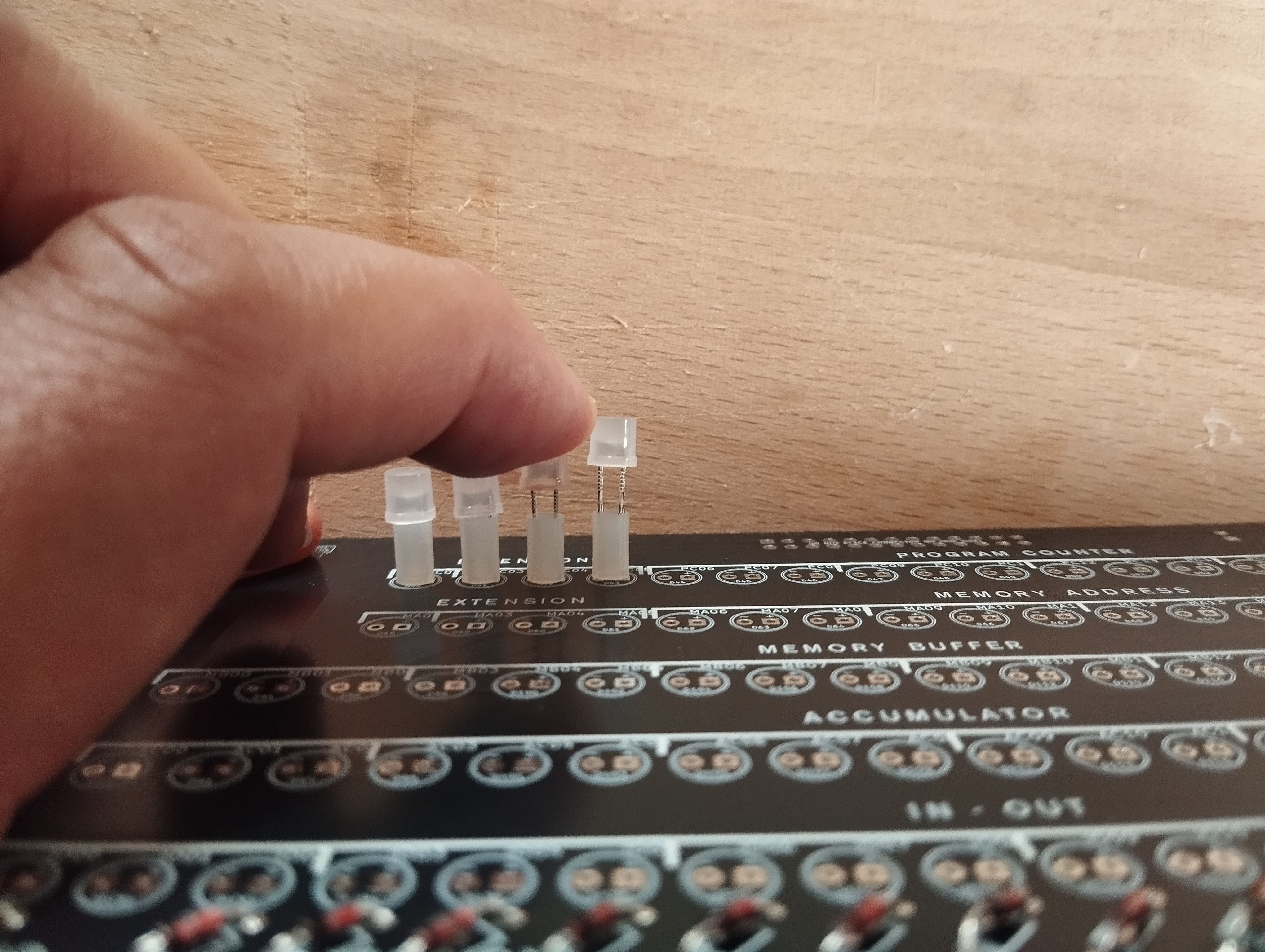 Pushing in the LEDs. Make sure not to bend their legs put them in. They should sit up neat and straight.
Mind, LEDs have a long + pin and a shorter – pin.
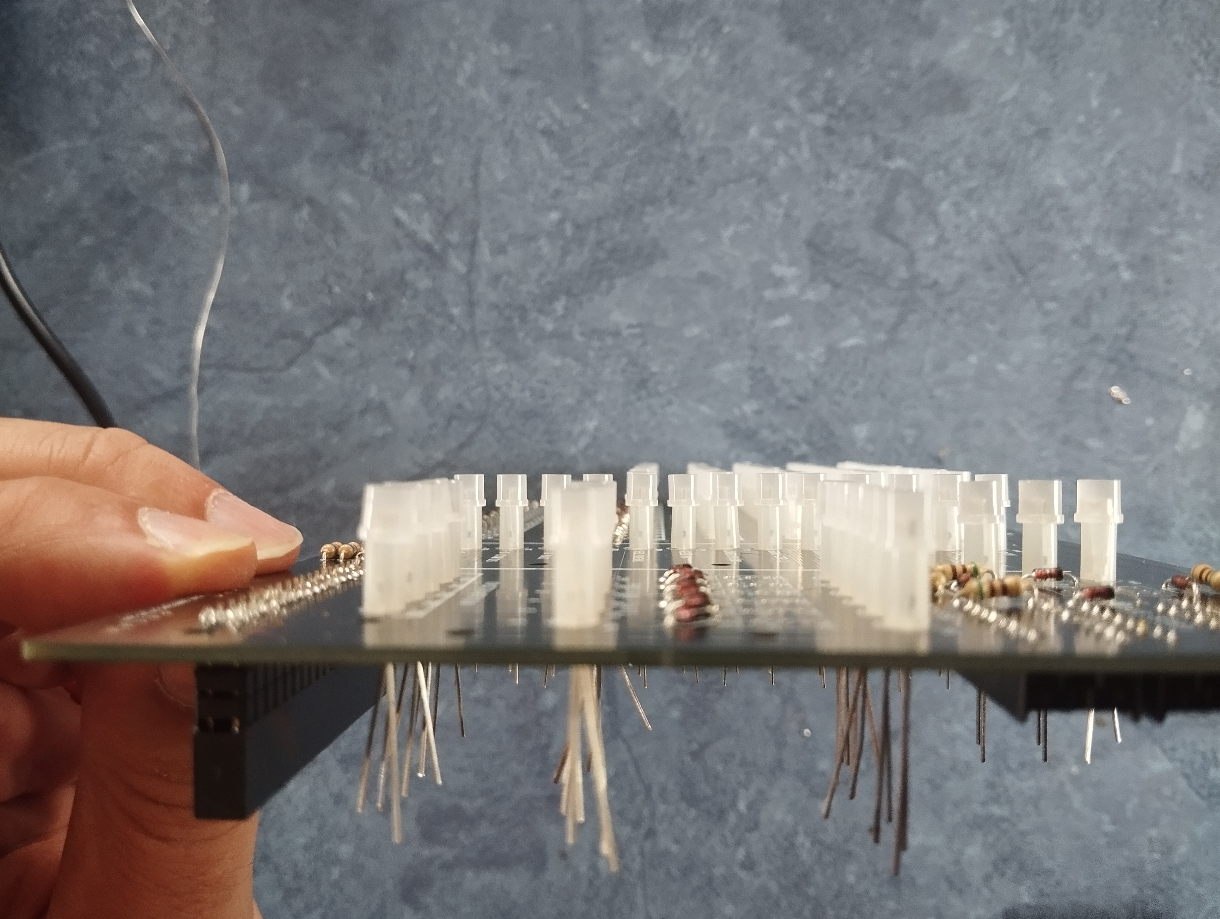 Check from the side if all LEDs are fully pressed in. Also, check that all LEDs have their long pin on the correct side. Which is the right side seen from the front of the PCB, but on the left side because you’ll be looking from the back of the board!
Now, put on the Ottopanel, board Ref.#8. Its purpose is to hold the LEDs in precisely the right spot. It will become a part of the case in a next step. Some of the LEDs will not voluntarily find their way into the mount holes of the Ottopanel, preventing it from clicking into place. Shift and wobble the Ottopanel to force the LEDs into compliance, but not with too much force. You might bend some LEDs, making it more difficult.
Some tips when fitting the Ottopanel
You could use some tape on all four sides of the Ottopanel to fix it to the main PCB tightly. make sure to remove the tape before going to the next step, fitting the actual front panel cover. The tape is only intended to hold things together when you flip the boards over to solder up the LEDs.
 The Ottopanel is loosely fitted here, to begin. Not all LEDs are yet fully seated in the panel (the fidgety part)
Ignore the switches visible in the photo. They should not be there yet.
 The Ottopanel is fitted, all LEDs neatly peeking through the holes in the Ottopanel (the fidgety part is over)
Ignore the switches visible in the photo. They should not be there yet.
 Once the Ottopanel is fitted, flip around the board set, and press it down (best: on a tablecloth) to keep all the LEDs pressed in evenly.
Solder ONE pin of each LED. Flip the board, check the LEDs are indeed neatly aligned. If one that does not, reheat & reseat it. Then solder the second pins.
Soldering the switches
Next step: place the 44 small switches onto the PCB. The Ottopanel helped to speed up the soldering of the LEDs, you'll now fit the actual front panel on top of the Ottopanel to speed up the soldering of the switches. And the other benefit of this two-step approach is that it makes the actual front panel exchangeable. You have a white and a blue one, your preference may change over time :-)
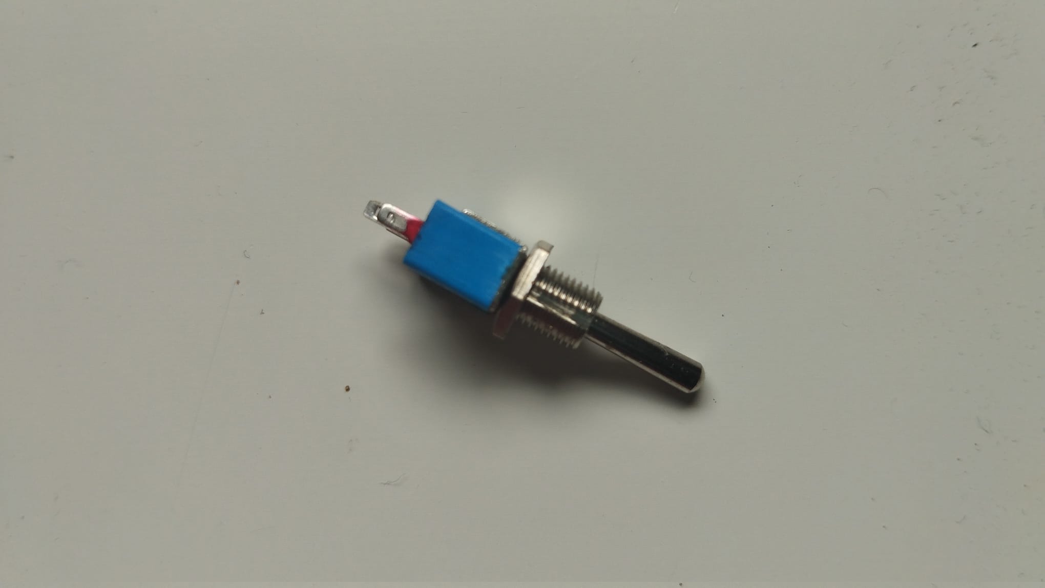 Switches have no polarity, putting them in upside-down is not a problem. But note the little groove in their screw threads? For cosmetic reasons, put them all in with the grooves facing down.
 The switches have been pushed, through the Ottopanel, into the PCB. They will sit there all wobbly for the moment, because the Ottopanel leaves them too much space. That is the point, though --
 Now fit the actual front panel (Ref.#10 is blue, or Ref.#12 is white) onto the Ottopanel. Make sure the switches find their way through their front panel holes. You might also need to fidget a little to get the LEDs into their new holes. But not much.
At this point, the switches are put in position, but of course not yet soldered up. If you would flip over the panel to solder their pins on the back of the PCB, they would just fall out. Now there are two ways to solder the switches; we prefer method #2, it is fast and has good results - even though it might seem a bit crude:
- Hold the PCB set, pressing a finger against a switch whilst soldering its middle pin only.
-
- Put some tape over the switch tops of each row of switches, so the switches are somewhat held together in the right position - they can now only wobble together.
- Place a flat bit of cardboard (better, a wood cutting board from the kitchen) on the top of the switch handles, so they’re all pressed into place.
- Flip everything over on the table and solder all the switches in one go – but just their middle pins.
 In the photo, we placed three nuts next to the switches onto which you have to screw them. That will attach the PCB to the Ottopanel and to the front panel. You can put nuts on more switches if you like, but these three are the minimum.
 Close-up of the nuts on the switches
with the nuts put on them
 But one last picture of what you have constructed. We call this the Sandwich, a combination of PCB + top Ottopanel + top frontpanel. It's ready to be mounted in the case.
 Note: your photographer forgot to put the solder tabs on. Don't make that mistake!
Bottom PCB: the 8 control switches
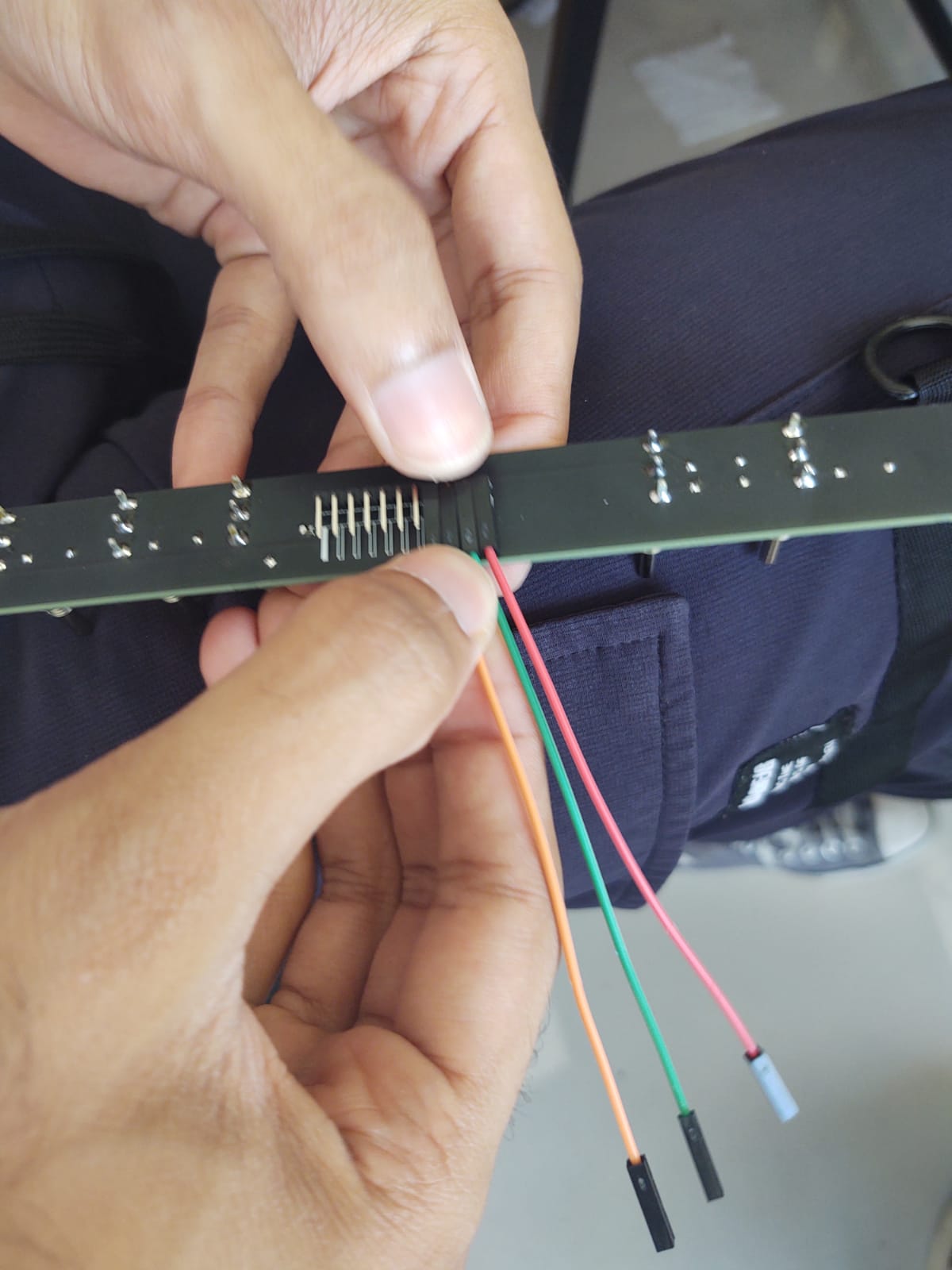
On to the much smaller switch PCB, Ref.#15.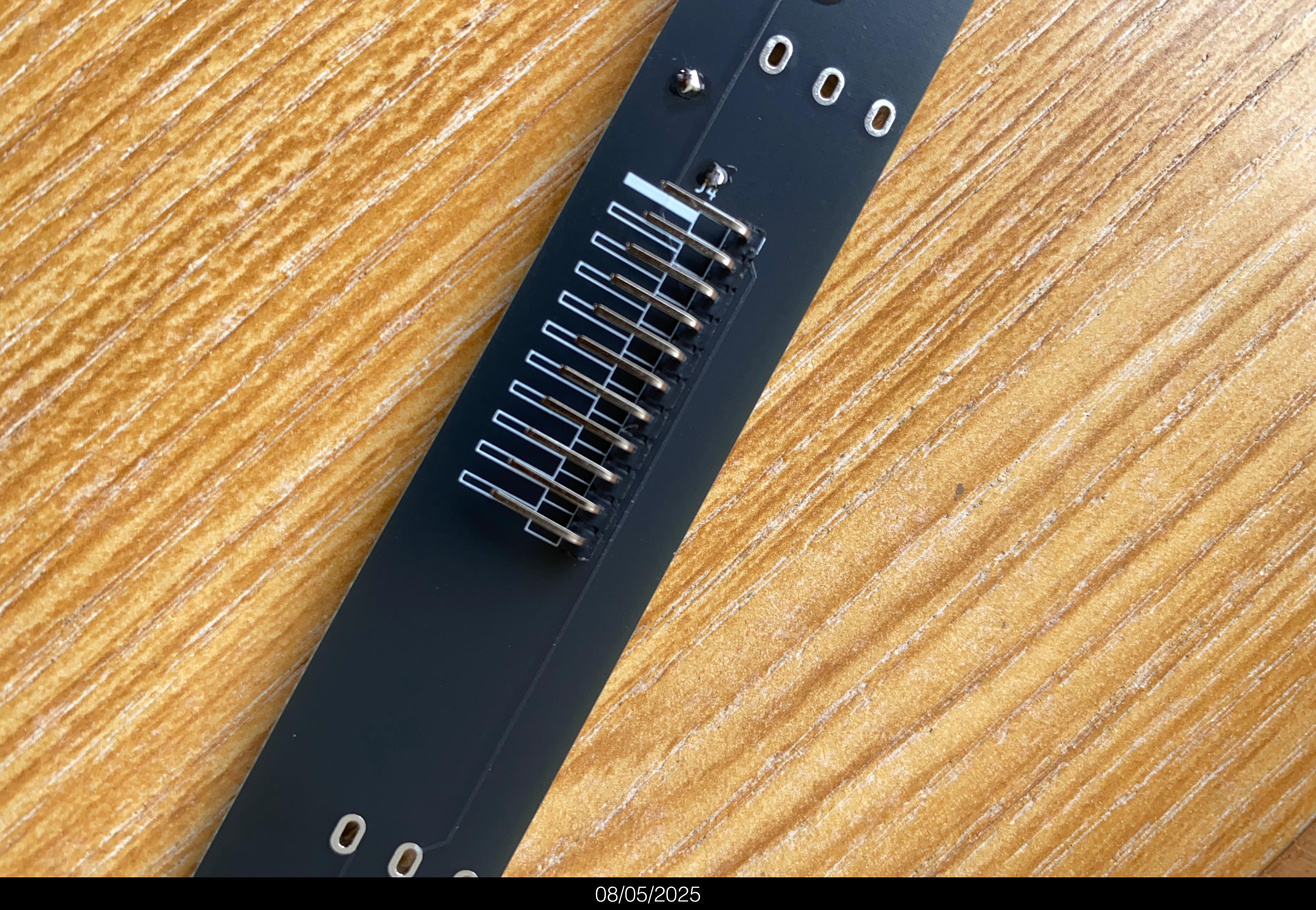 Solder the angled 1*11 pin header (the angled one, not the straight one!) on the BACK of the PCB.
Avoid soldering in the angled header pointing down towards the PCB. Better let it point up a little bit, to easily fit the rainbow cable connectors.
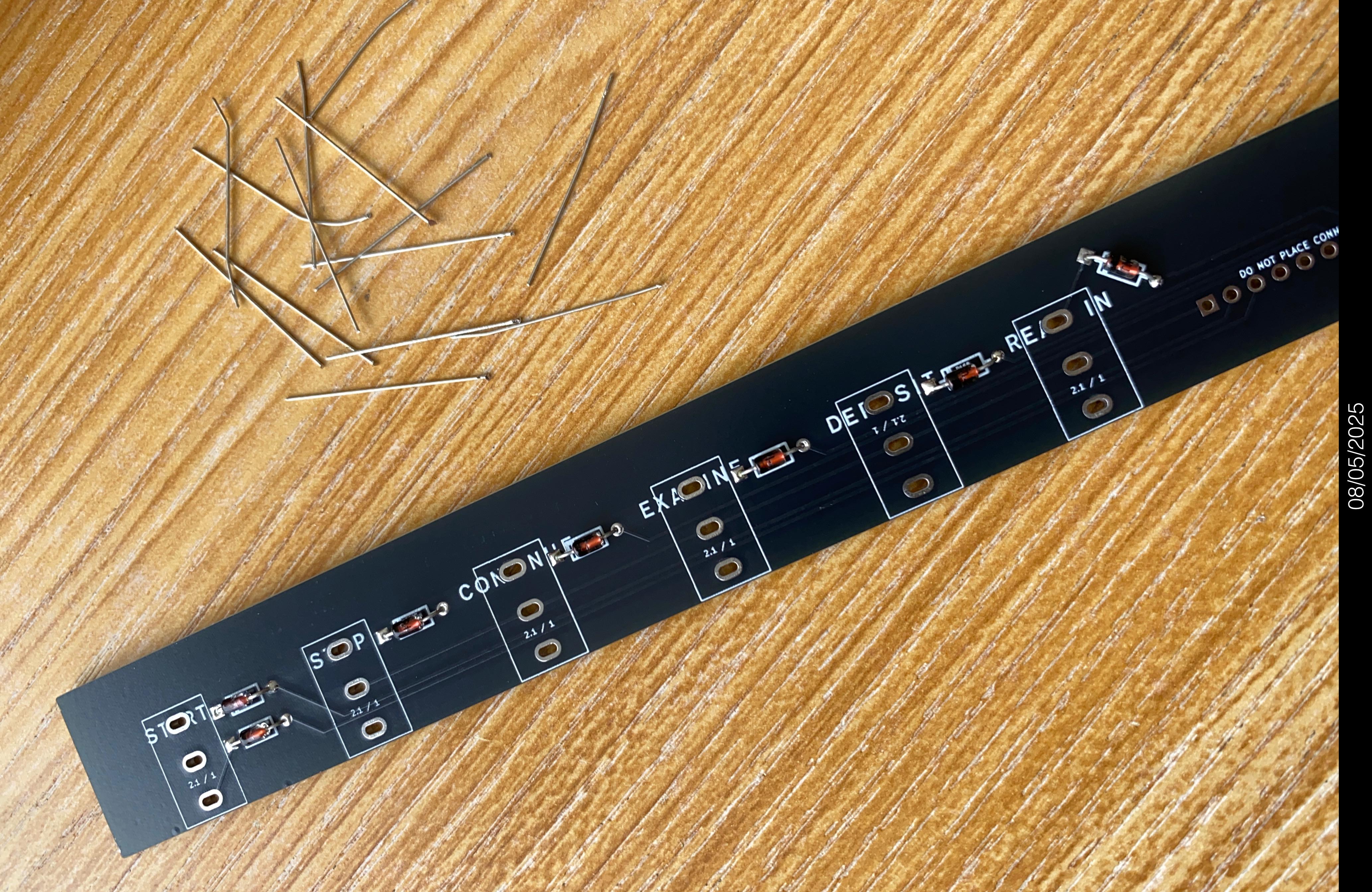 Solder the 10 diodes on the front.
Again, do not overheat switches. Apply the soldering iron for at most 7 seconds at one time. Do all the lower pins first, then all the top pins. So the switches get some cooling off between each pin being soldered.
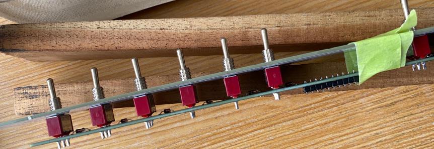 Put the 8 switches into the PCB.
As a mounting help, put the Ref.#11 blue lower front panel cover on the top, over the wobbly, because as yet unsoldered switches. Even better, also put the Ref.#13 white lower front panel cover on top, too. You can put a bit of tape around it all to hold things in place. Put a nut on each switch, and tighten lightly. Now, solder up the switches.
3. Test the PiDP-1 to see if everything works
A quick test before you continue soldering
Finish the electronics
- Insert the 3 ICs into their chip sockets on the main board.
From top to bottom, the ICs are UDN2981/TD62783AP (P1), 74HC238 (U1) and 74HC138 (U2)
...and because it happens, if you swap the 138 and 238 around by mistake all the front panel lamps will always be lit up.
...another common mistake: putting the ICs in the other way around. Mind the notch, match with the footprint. - Plug the 11-pin ribbon cable into the switch PCB and on the other end, into the pin header on the PiDP-1 main board.
- Insert the prepared Raspberry Pi.
Power up the Pi after you've connected the HDMI and keyboard cables.
Open up a terminal and type:
														pdp1control stop

														/opt/pidp1/test.sh
See if all the LEDs work. Note the ones that do not, and check their soldering.
If that does not solve the problem, see the page Debugging the PiDP-1
See if all the switches work. Note the ones that do not, and check their soldering.
If that does not solve the problem, see the page Debugging the PiDP-1
Before you think that the DEP switch does not work: the DEP switch works the other way around - you have to push it UP, not down to get a signal!
4. Mount the PCB + top front panel into the PiDP-1 case
A note for Rack version builders
The Rack version, of course, comes with both the Console and the Rack case. You should mount the PCB set into the Rack case first. That means that you will solder the Ottopanel, which is now part of the PCB set, onto the Rack case.
Once that is done, you should consider the white front panel as a spare Ottopanel, and solder that onto the Console case. Then, you can transplant the PiDP-1 circuit boards between the Rack and the Console case at any time.
But first, follow the instructions to mount the PCB set into the Rack case. The console case is for later.
Put the top of the front panel onto the PiDP-1 case
This works the same for the Console and the Rack cases:
take the sandwich of PCB+top Ottopanel+front panel, and slide into the front of case. Position it so that it sits tightly against the switch panel (the #9 that is already part of the PiDP-1 case). You might need to bend the three little solder tabs in a bit so they stay clear of the bottom Ottopanel.
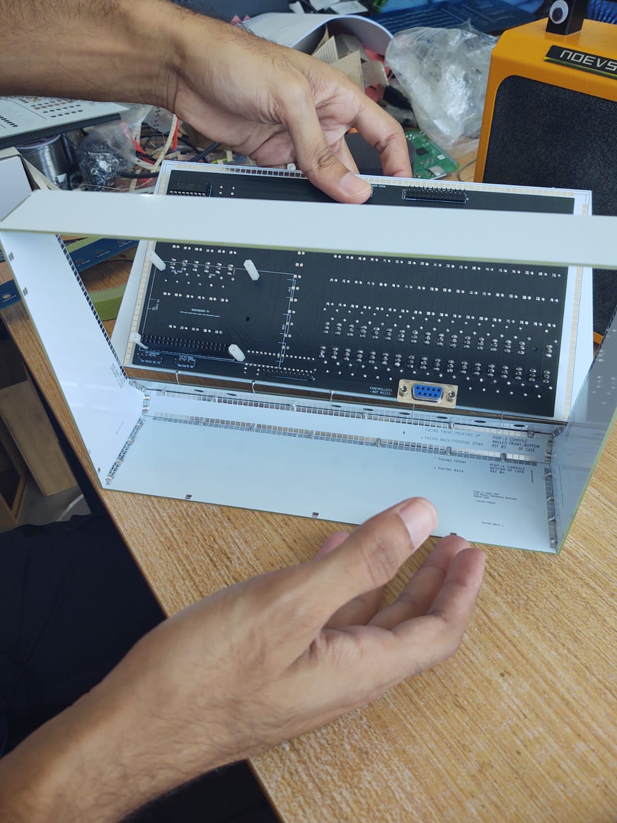
Place 'the sandwich' (of PCB+top Ottopanel+front panel) on the bottom Ottopanel (which already part of the case) and push it into the case.
Close it up...
...Close it up further...
Use a bit of tape once you're happy with the horizontal positioning (lower corners of top Ottopanel lines up perfectly with the corners of the bottom Ottopanel). The switch PCB, Ref.#15
Tape it up...

Looks good. But will look better once the back panels are clipped in, later on!
Details before you decide that the 'sandwich' is aligned perfectly vs. the bottom front panel
...make absolutely sure that alignment is precise:- Horizontally: its bottom corners exactly match the top corners of the switch panel. You don’t want them to be misaligned.
- Vertically: it sits flush against the switch panel. Note how they touch each other: the top Ottopanel sits a tiny bit higher than the bottom Ottopanel. The same will be true for the front panel cover put on top of the Ottopanel, and it is this mix of factors that gives precision and strength to the whole construction, so that you do not notice the front panel consists of two parts. You'll see :-)
- The reference points to get right (all that matters) are:
- Horizontally matched to the switch panel (not shifted left or right)
- Vertically, the bottom edge of the Lights panel sits tightly against the top edge of the Switch panel
Solder the top of the front panel to the case
To be precise: after you've lined up the top Ottopanel so it precisely fits with the bottom Ottopanel, as per the section above, you can now solder the sides and top edge of the Ottopanel to the PiDP-1 case. Do one solder point per side first, and check if indeed the two halves of the front panel are still neatly aligned. If not: reheat & reseat. If the alignment looks good, solder up all the other solder points as you did when you constructed the case: solder one in five solder tabs together, that is more than strong enough.
Soldering the Ottopanel to the case. Remember: Only do one solder spot per side (left, top, right), then check for alignment of top and bottom panels again! If not perfect: reheat & reseat. If perfect: zip up the sides with more solder spots. If you do one out of every five solder pads, the case will be indestructible, that's enough.
Bend the little solder tabs at the bottom of the top Ottopanel so they sit against the matching solder tabs of the bottom Ottopanel. Solder them up whilst pressing top and bottom Ottopanel together, so there's no air gap between the two halves of the front panel. Instead of pressing, you can also use tape to fix the two parts tightly together before soldering.
A fix that some builders may need
For the second and later batch of kits (after 2025):
Some builders noted that the panel lamps on the top left are not fully pushed through the front panel. It depends on the tension between the Ottopanel and the PCB. But for some, if they push on the PCB behind it, the LEDs come out more on the top left. Once you see it, you can't unsee it! Annoying.
Here is the solution.
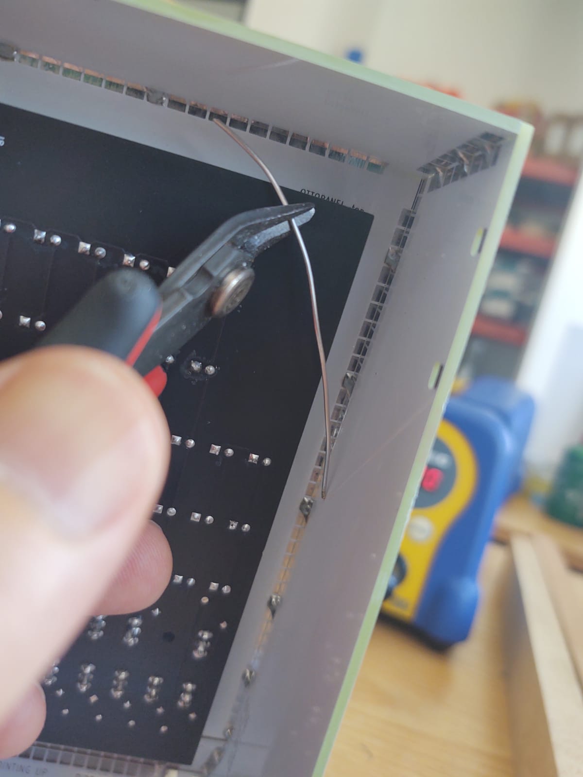
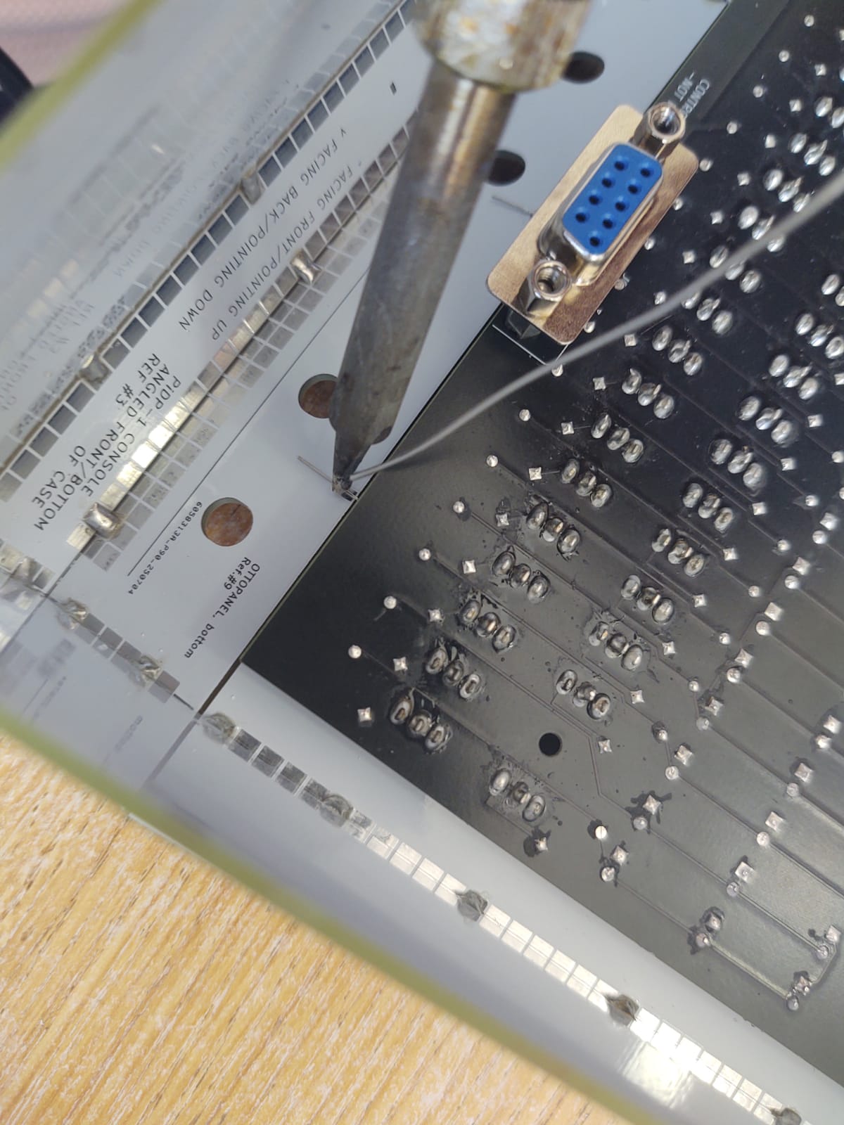
Bend a clipped-off LED/diode pin in an L shape and solder it on the top-right (when viewed from the back) of the Ottopanel. Let it stand up straight and route it through the little pinhole of the PCB. Then, just bend it. It will keep the PCB pressed against the panel.
For the first batch of kits (2025):
In case you have a PiDP-1 from the first batch, we liked to think that this was a quality hack for a design imperfection:
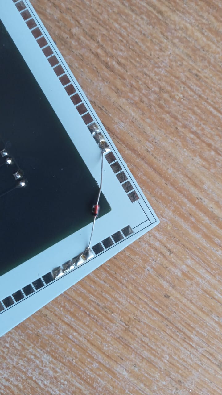
Solder a wire or spare resistor/diode across this corner of the main PCB. Because there's no switch on this part of the panel, there's no nut on a switch to fix it tightly. It looks like a hack, it smells like a hack, but it is a perfect hack. In 2025, we preferred it over adding a tricky-to-align solderable bolt nut.
Mount the small control switch PCB in the case
This works the same for the Console and the Rack cases. We show the Console case, but it does not matter.
First, put two spacer nuts on each of the 8 switches.
Put the 11-wire rainbow cable on the switch PCB
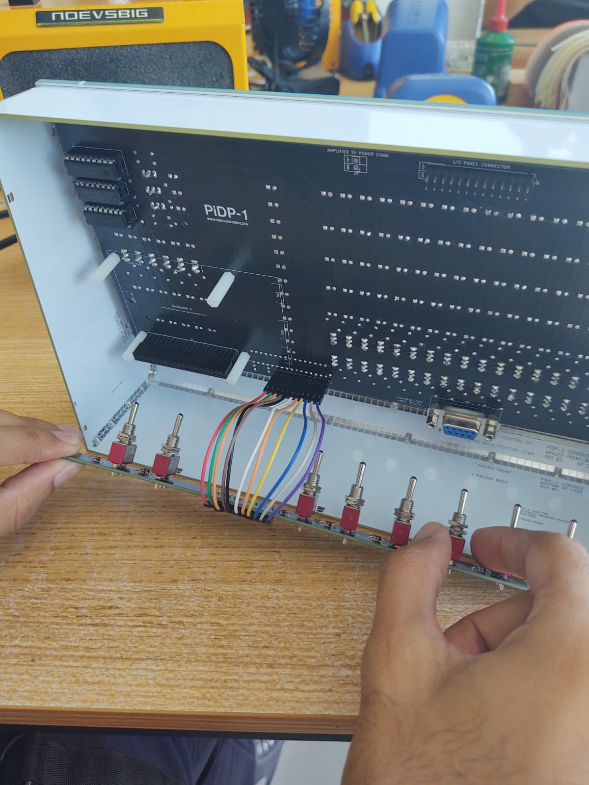
Make sure each of the switches has the two spacer nuts already on. Insert the PCB (you can first connect the rainbow cable, as here, or do it at the end)
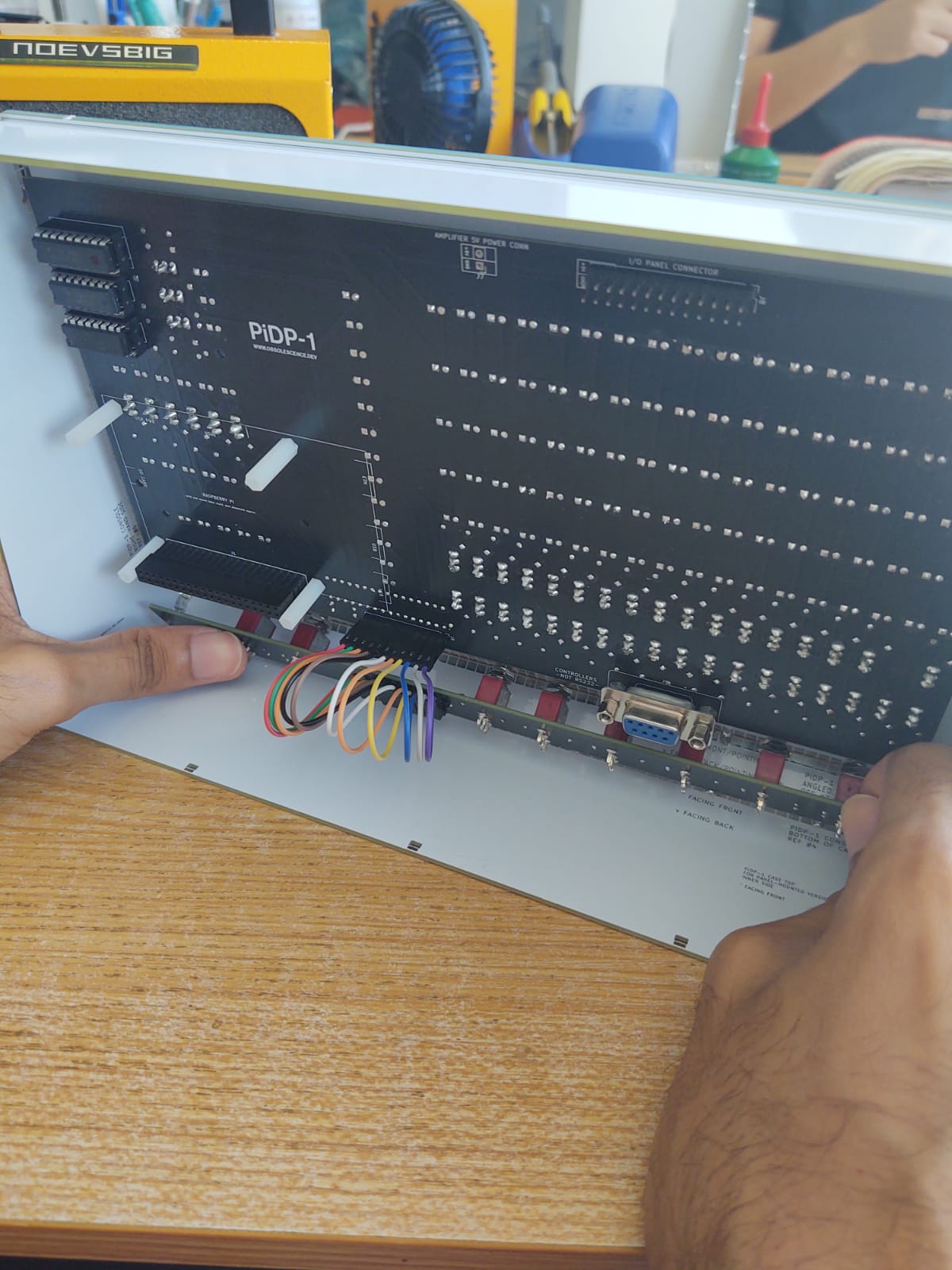
...in position...
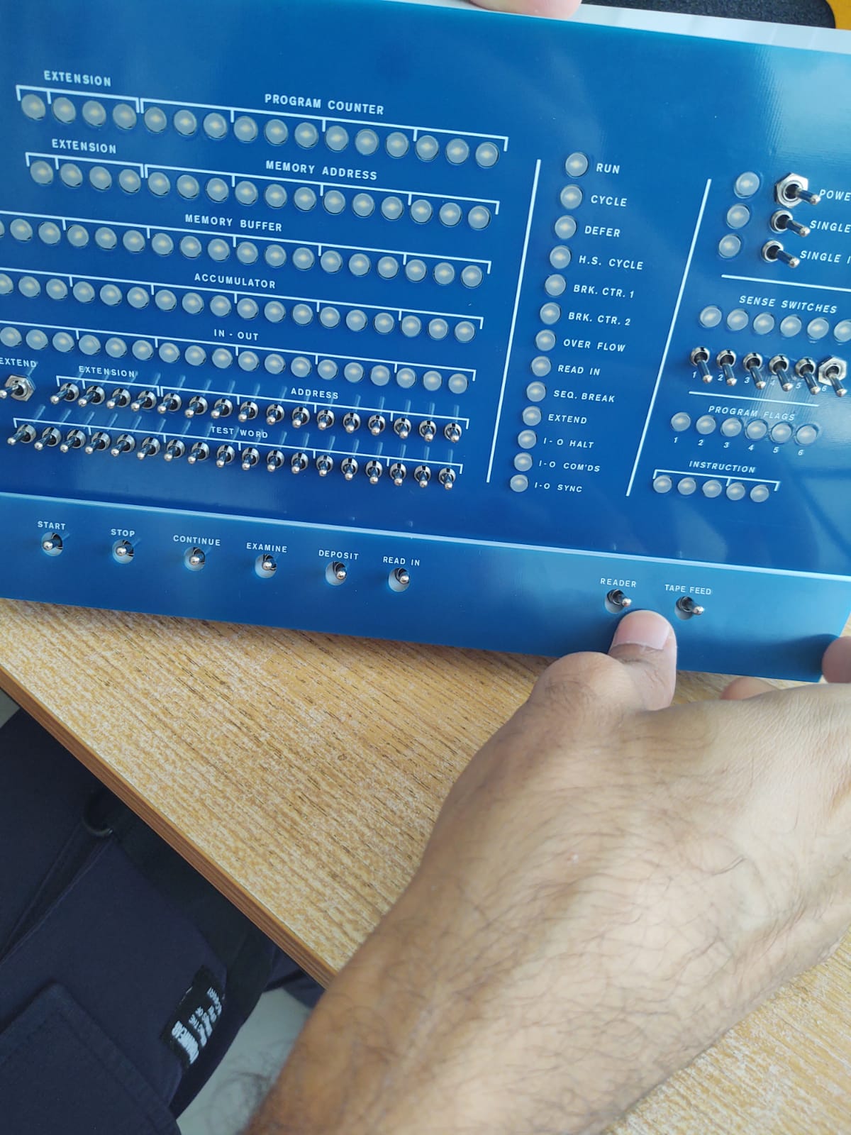
Now, mount the actual bottom front panel (blue or white, your choice)
Put bottom front panel in its perfect place:
Add a nut to two of the switches, loosely, to keep things in place. You might have noticed the mount holes for the switches are ovals. And here is why: slide/push the (here, blue) bottom front panel up as far as it can, tight against the top front panel.
Put the nuts on all the switches, and that tightens everything up. Done.
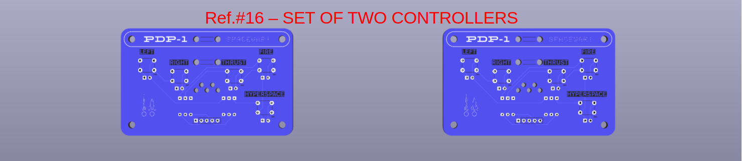
5. Build the game controllers
The two controllers
The 'spacewar' game controllers are simple to build. This will be the end result:
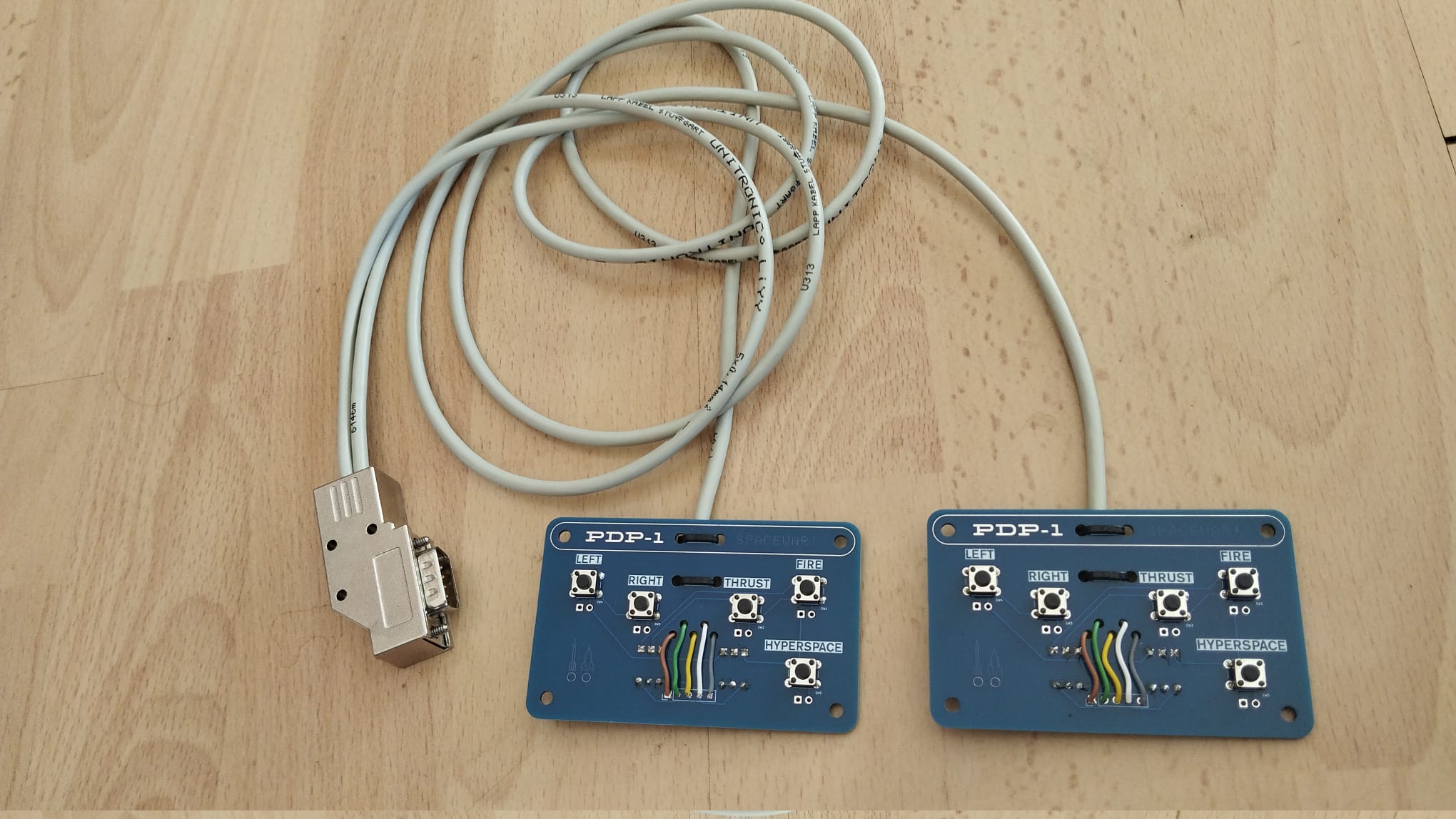 The assembled spacewar game controllers
 Front side
 Back side
If you have a 2m long single cable, start with cutting that supplied cable into two pieces, one for each controller.
On both ends of each of the two cables:
- Cut off about 2.5cm of the cable's mantle (the outer plastic) to reveal the 5 wires inside.
Tip: keep the cable in a sharp bend while you cut the mantle. Only a few shallow cuts will suffice to let the mantle tear itself open. - For each of the 5 wires inside, remove about 3mm of the insulation. A sharp knife will do the job.
- On each wire, turn the copper strands a few times to make them stick together, then tin the ends with a bit of solder.
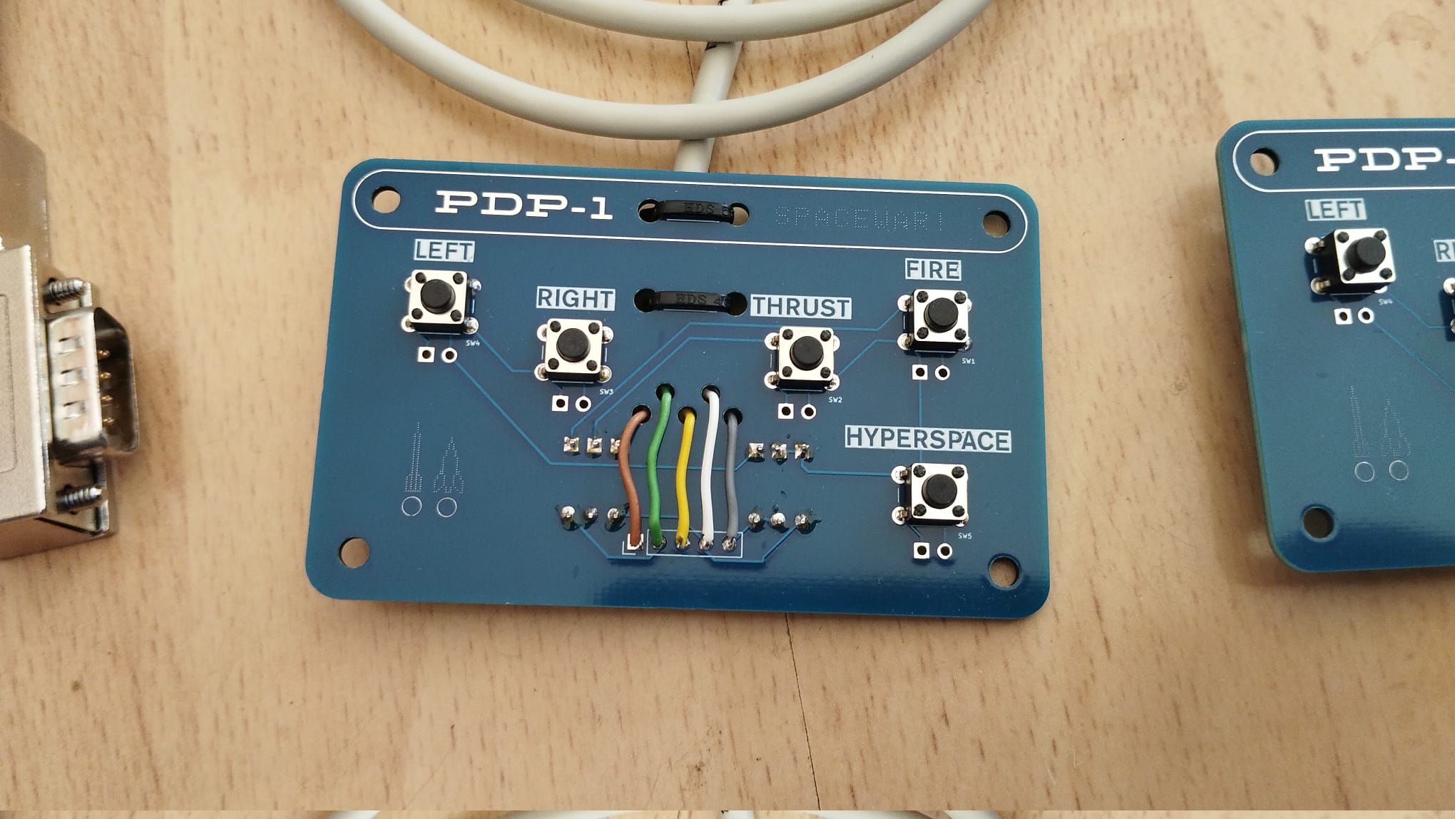
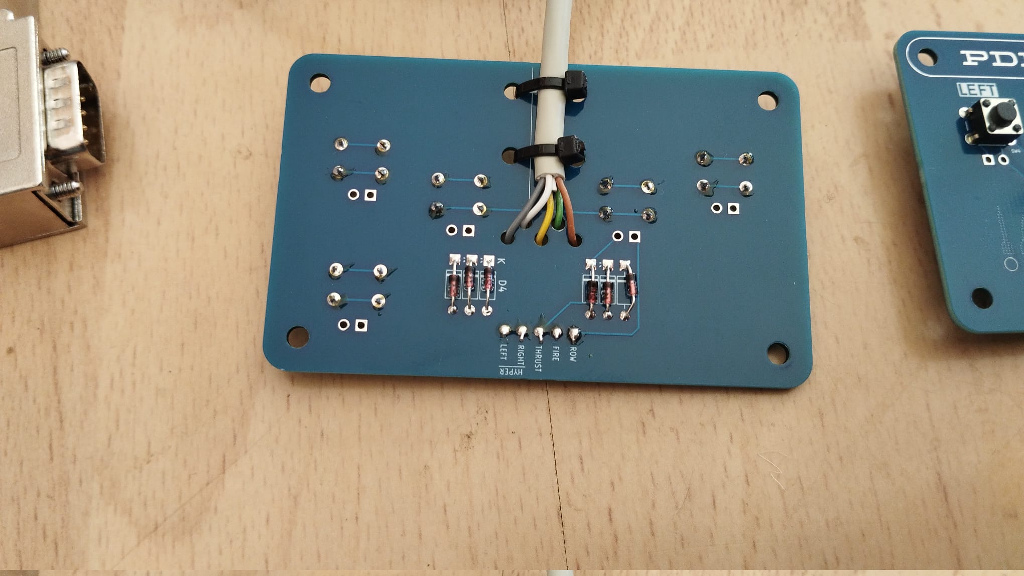
- solder on the 5 tact switches
- solder the 6 diodes
- mount the 5 wires from the cable
- use 2 tie wraps to tightly hold the cable in its place at the bottom of the PCB
For future kit builders: perhaps we will not always source cables with the same set of colours inside. If your cable contains a different mix of colours, just make a little translation table from the colours in the pictures to the actual colours inside your cable.
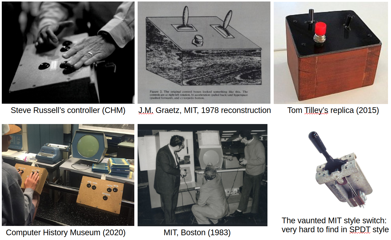 The game controllers are kept very simple for a reason.
They have a second purpose: they can also serve as the PCBs inside homebrew controller boxes. If you google around on 'PDP-1 spacewar controllers' you will see that it is a good tradition to make spacewar controllers from a clunky wooden box and some old retro switches. Even in the 1960s, there were many variants using all sorts of switches, levers, buttons. Below is some inspiration, if you are tempted:
So if you want to keep that tradition: find yourself two wooden boxes and some old switches (especially the lever types are hard to get, hunting for them is a in fact hobby for some spacewar fans). Below each of the tact switches on the controller PCB you will find a footprint to solder wires to whatever switch you like. And then, the controller boards can serve as the PCB inside a proper homebrew spacewar box. That is why the controllers come with mount holes, to fit them into some box!
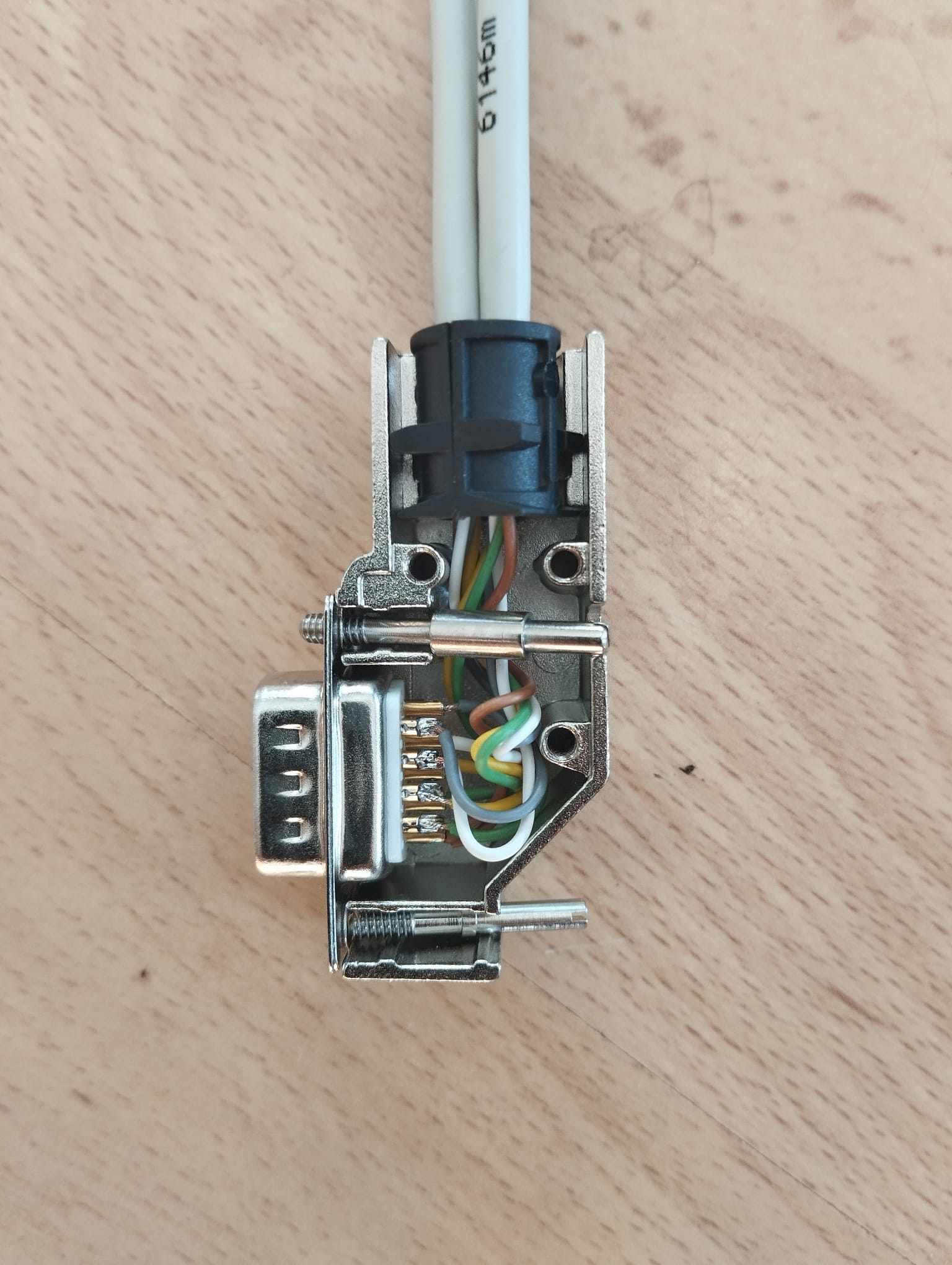
The DE9 connector on the other end of the cable
Again, note the colour of each wire, and the order into which they are soldered on the game controllers. Then, solder the coloured wires to the connector in the pin order as shown in the pictures below. As always on this page, click to zoom the images.
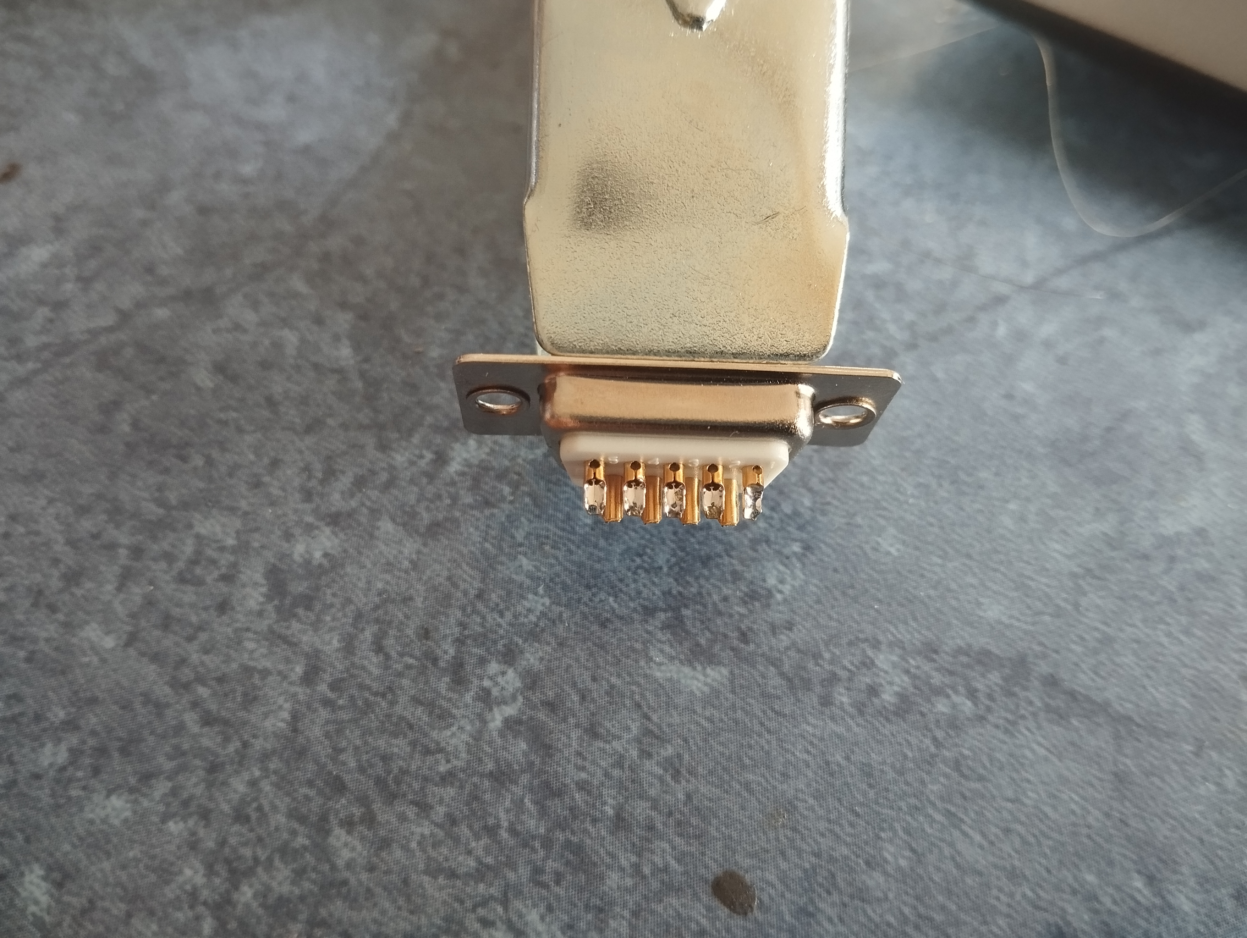 Use some sort of a clip or clamp to hold the connector. It makes the soldering much easier.
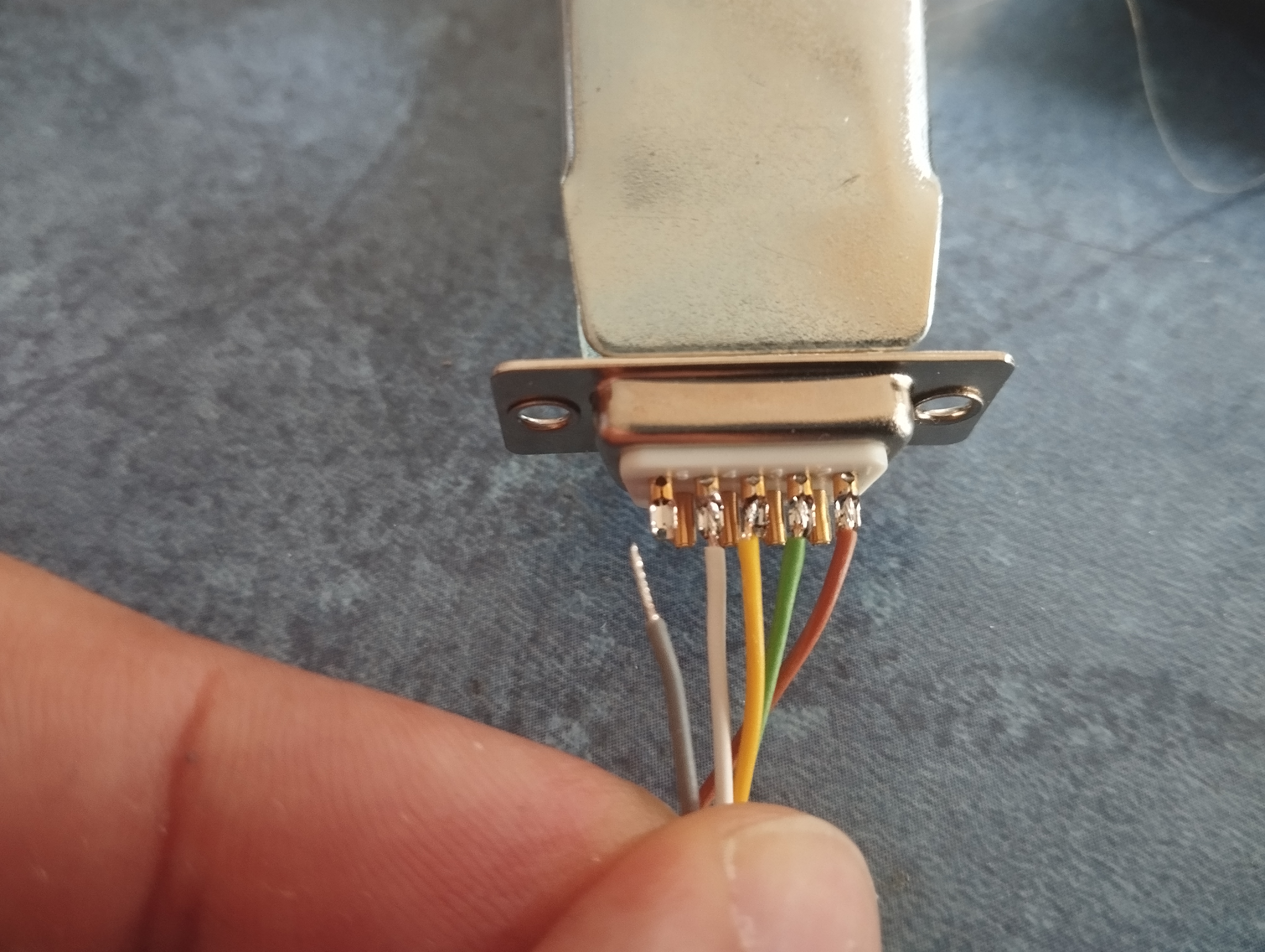 Start soldering the wires from a controller, like so, on the bottom row of the connector - the row with 5 pins.
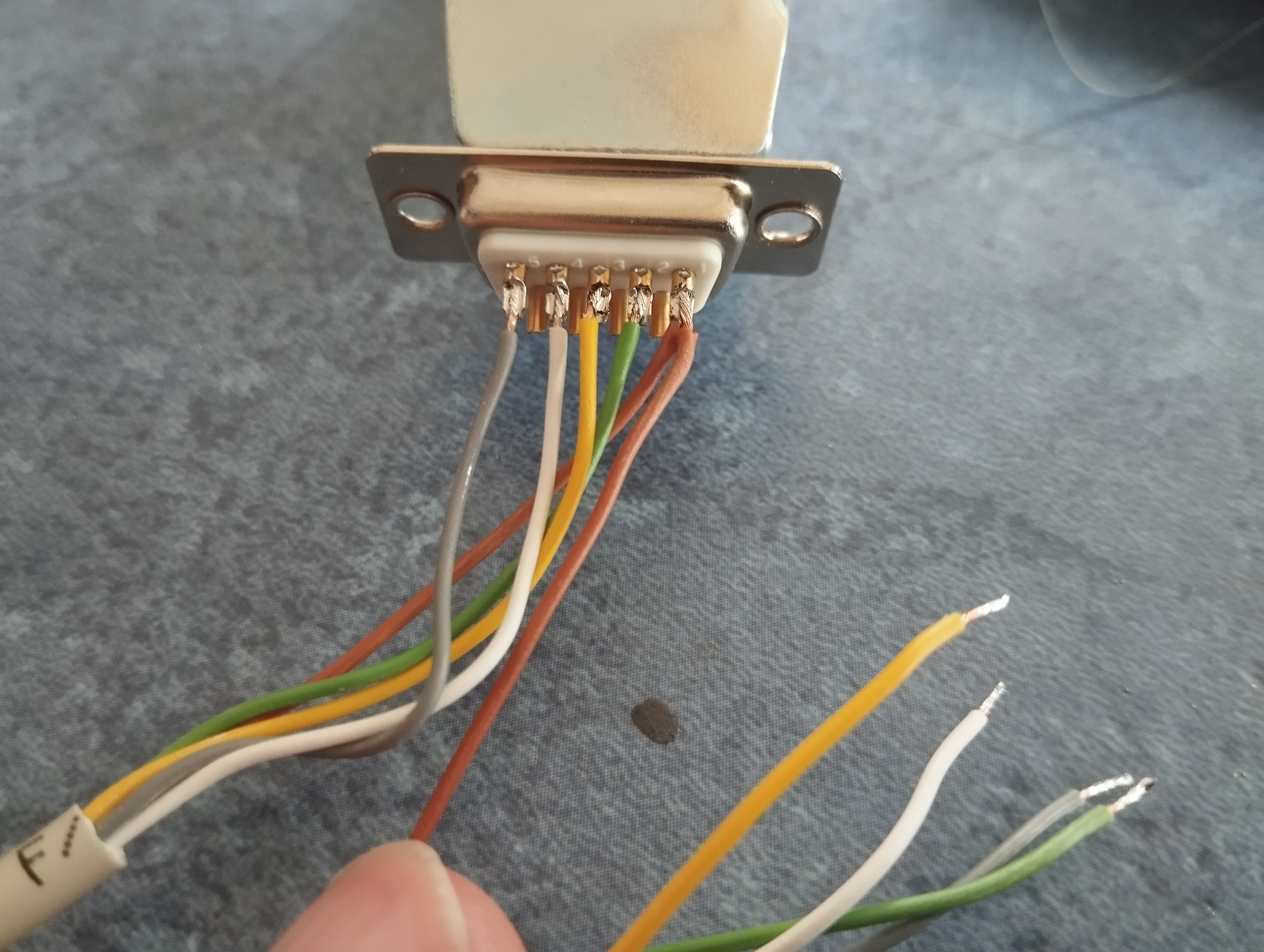 Adding the wires from the other controller - note that its brown wire shares the same pin as the brown wire of the first controller!
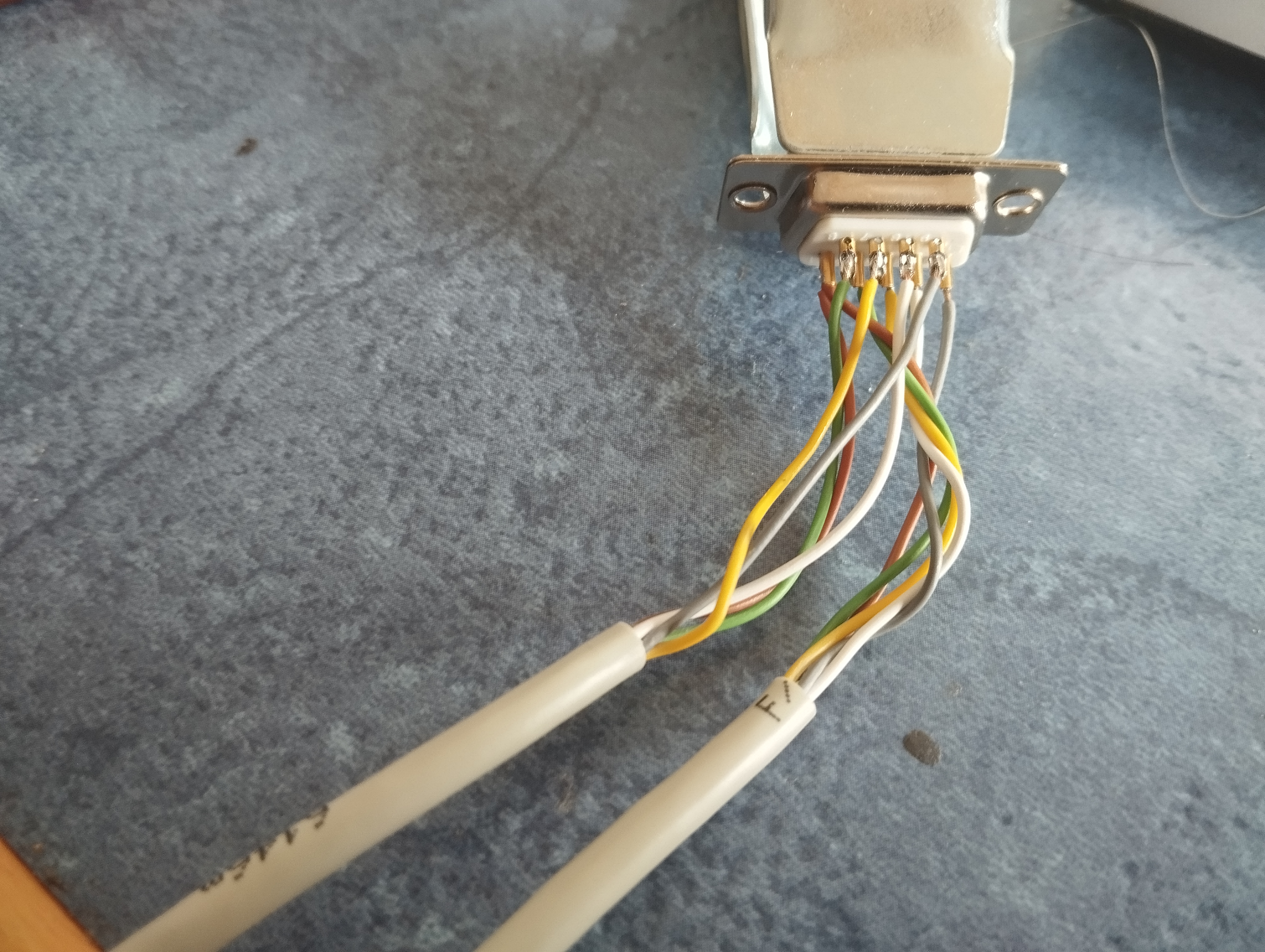 The other wires of the second controller go on the top row of pins. Note that I turned the connector upside down for this shot.
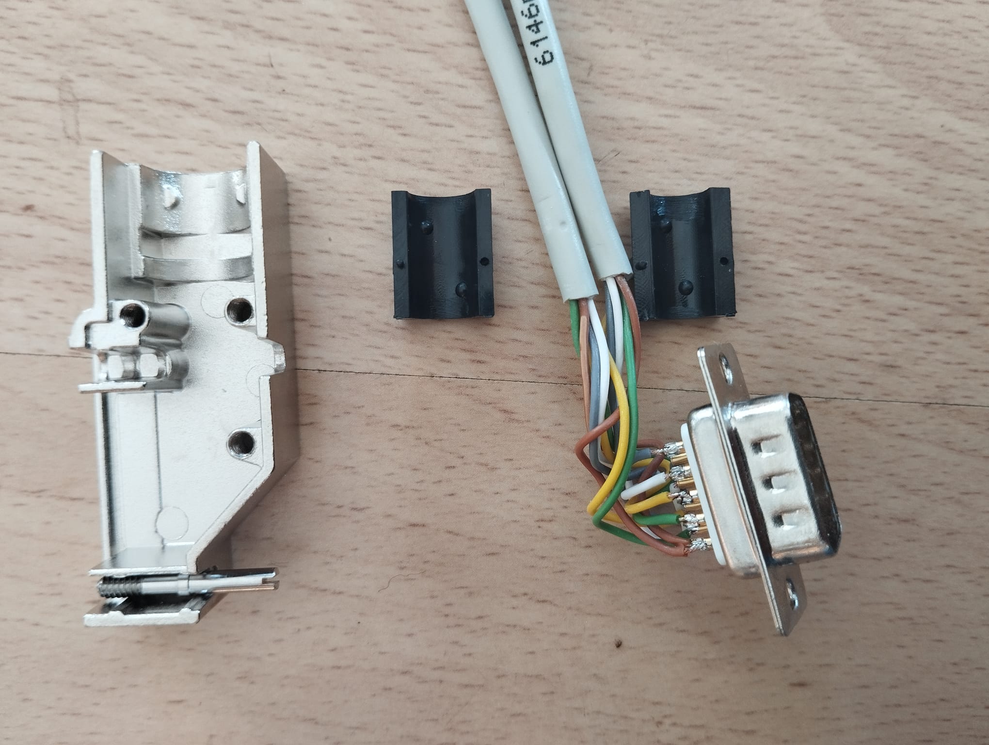 The connector case has plastic blocks that surround the cables
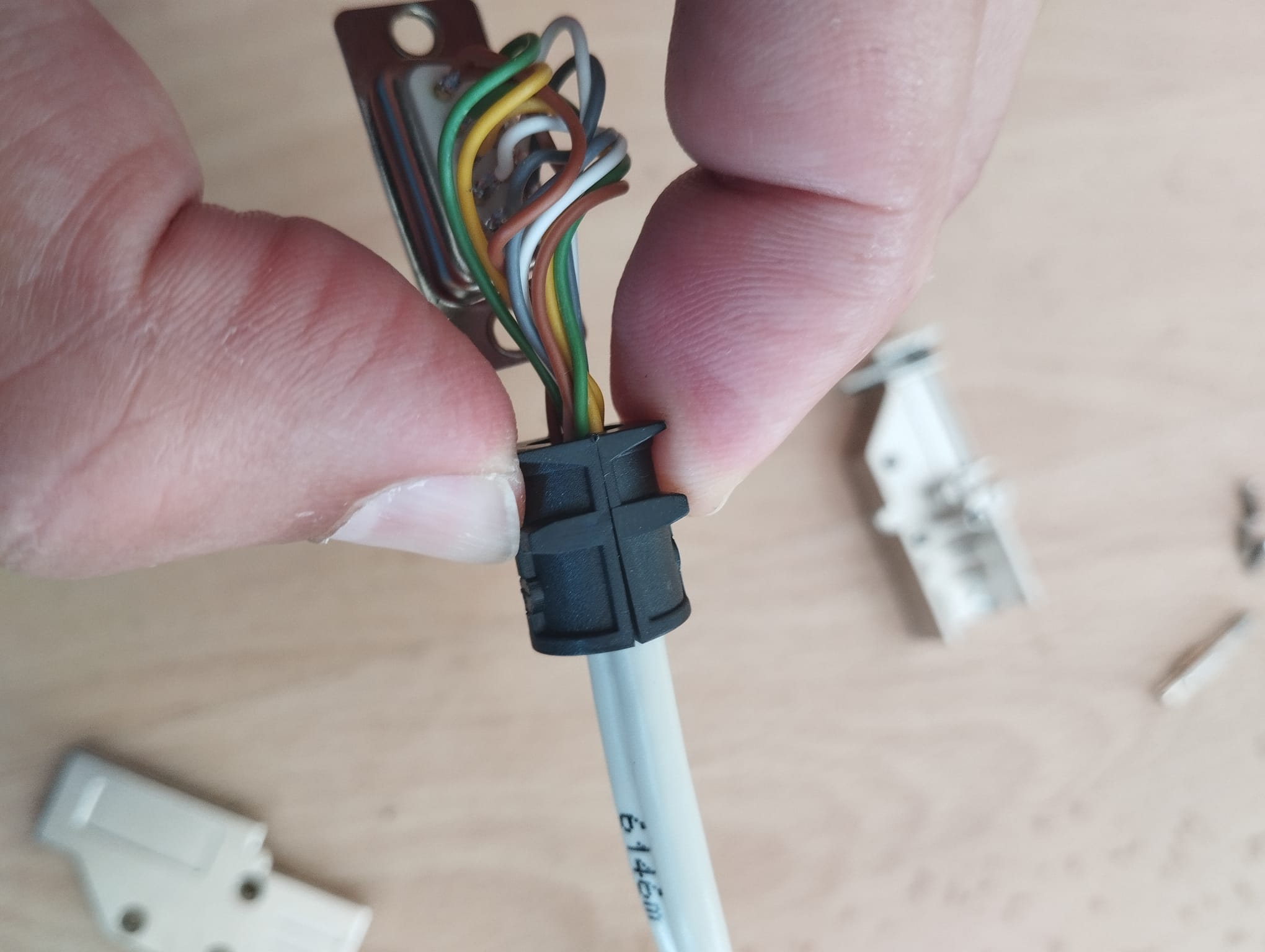 Put them around the cables, then put the clamped-together blocks in the connector case
 The other wires of the second controller go on the top row of pins. Note that I turned the connector upside down for this shot.
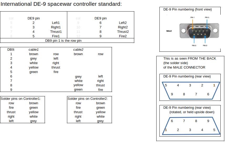 Wiring diagram, in case of doubt and confusion.
Note: the connector case supplied with the kit may vary from the one in the photos. But the same principles will apply nevertheless.
Note: if you get confused by the colours, or want to make sure you understand the wiring, the pinout in the last picture can help. As always, click to zoom.
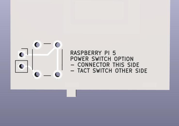
Optional: add a power button for the Pi 5
Optional: add a power button for the Pi 5
The Raspberry Pi 5 has a tiny push button on its side, to power it on and off. Because this will be hard to reach when the Pi is mounted in the case, we added an external tact switch to fulfill its task. That tact switch can be mounted on the lower back panel (Console version) or on the left of the bottom rack panel (Rack version)
Building steps:
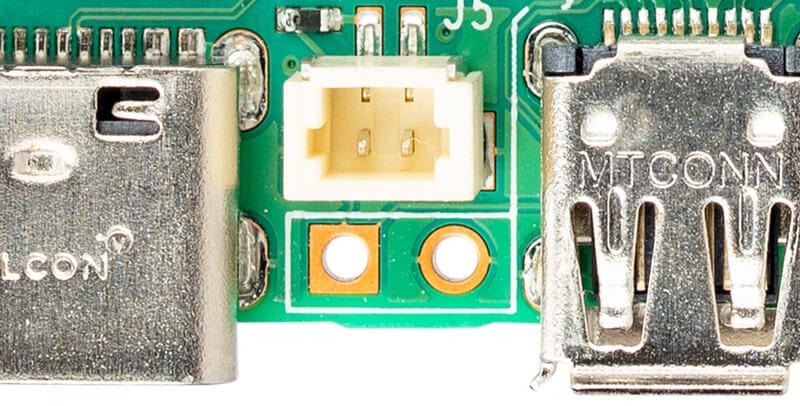 Solder a 2-pin header on the raspberry Pi itself
 Console version:
Solder the tact switch on the front, and a 2-pin header on back of the PiDP-1 Console back panel.
Connect the cable between Pi and PiDP-1 back panel.
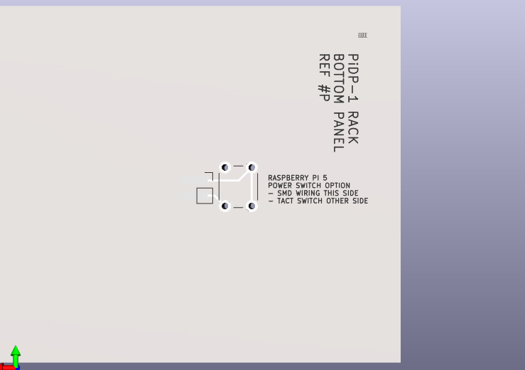 Rack version:
Solder the tact switch on the front of PiDP-1 Rack bottom panel.
Cut off one of the connectors from the 30cm F/Frainbow ribbon cable, and solder the wires (SMD style) straight on the back of the PiDP-1 panel. Connect the Pi with the other end of the cable.
Note: this is a harmless button - it does not really have 5V going through it. It signals to the Pi to wake up/go back to sleep. Inadvertently shorting the wire is not dangerous.
Note 2: Not many people use the Pi 5's power button anyway - previous Pi versions did not have it. You can skip this if you do not like soldering a pin header on your Pi 5.
If you are building the PiDP-1 Console version: congratulations. You are done!
All that remains is to bend in the top and bottom back panels, Ref.#1 and #2. You can just clip them in, or use the solder tabs to keep them firmly rattle-free.